Supercomputer Cluster Node
Table of Contents
Assembly
Parts List
- 37 LEDs - 5mm self-flashing
- 37 220Ω resistors
- [optional] USB jacks: CUI Devices UJC-HP-3-SMT for USB type-C and/or Amphenol 10118193 (or similar) for micro-USB
- [optional] 5.1KΩ resistors for USB type-C charge signaling
Process
As with most builds, it works best when you start with the smallest parts and work upwards. Start by soldering in the resistors, then do the LEDs. Since the USB jacks and associated signaling resistors are on the back, it doesn't matter when you do them.
Assembly Stand
I've also made a 3D printable assembly stand that helps with positioning the LEDs.
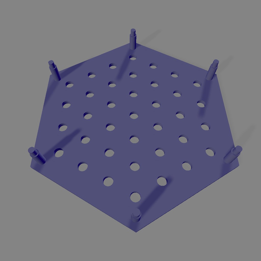
It works best if you do the resistors first, then insert all the LEDs pointing up, put the stand on top, then invert the whole assembly and shake it so that the LEDs settle in the holes. Everything should be more or less aligned for soldering in the LEDs.
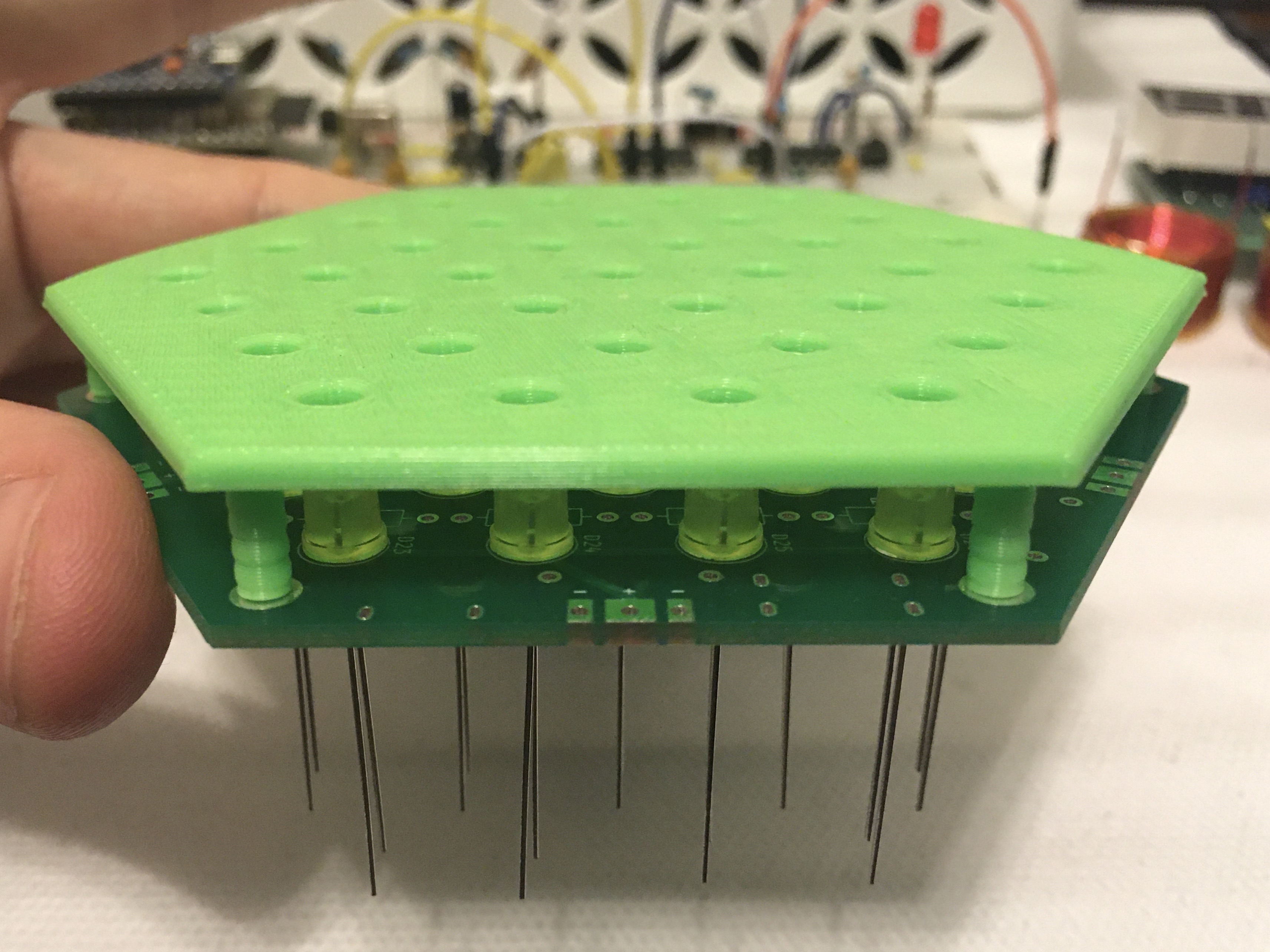
It's not perfect, but it's a lot better than doing it manually.
Specs
- Input Voltage: 3-6V DC
- Total LED Power Consumption: 1.67-2.96W (333-592mA at 5V)
- Per-LED Power Consumption: 45-80mW (9-16mA at 5V)
- Corner Hole Size: M2.5
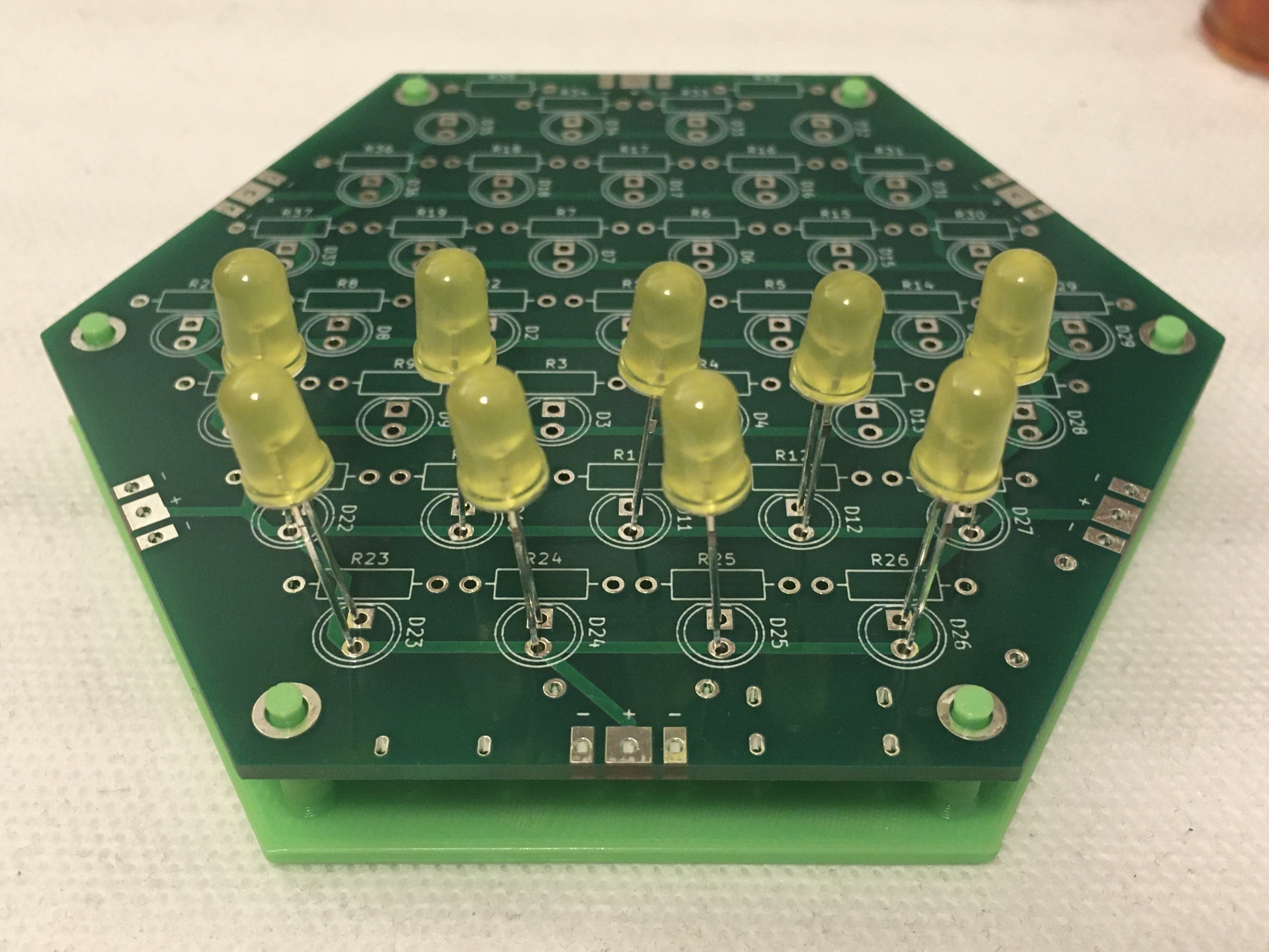
The Board
The board is a hexagon, 50mm on a side. This makes it 100mm between corners, and 86.6mm between sides. This puts it juuuust inside the limits of certain cheap PCB production services. :)
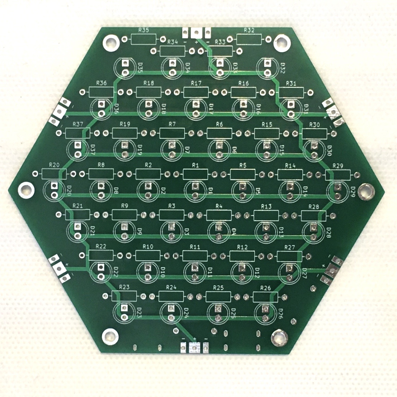
The front of the board has 37 LEDs, each with a current limiting resistor, wired in parallel. Because of this, it's not strictly necessary to connect all LEDs. If you'd rather, you can put them in selectively to create a pattern. The supercomputer effect is created by self-flashing LEDs, but you could put in standard LEDs for a static display, or mix and match for whatever pattern you desire. Each LED label has a matching resistor label. D1 goes with R1, D2 goes with R2, etc.
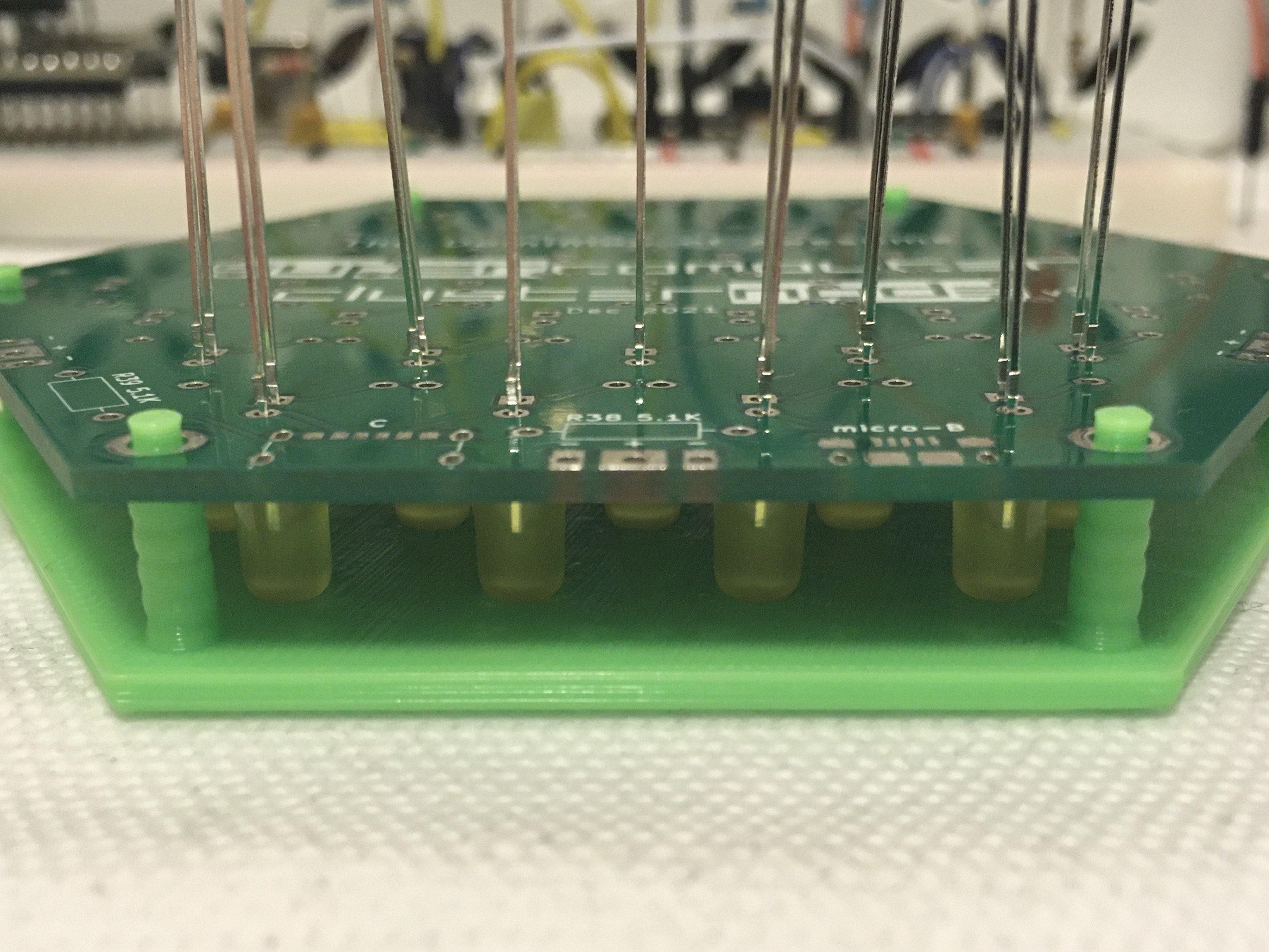
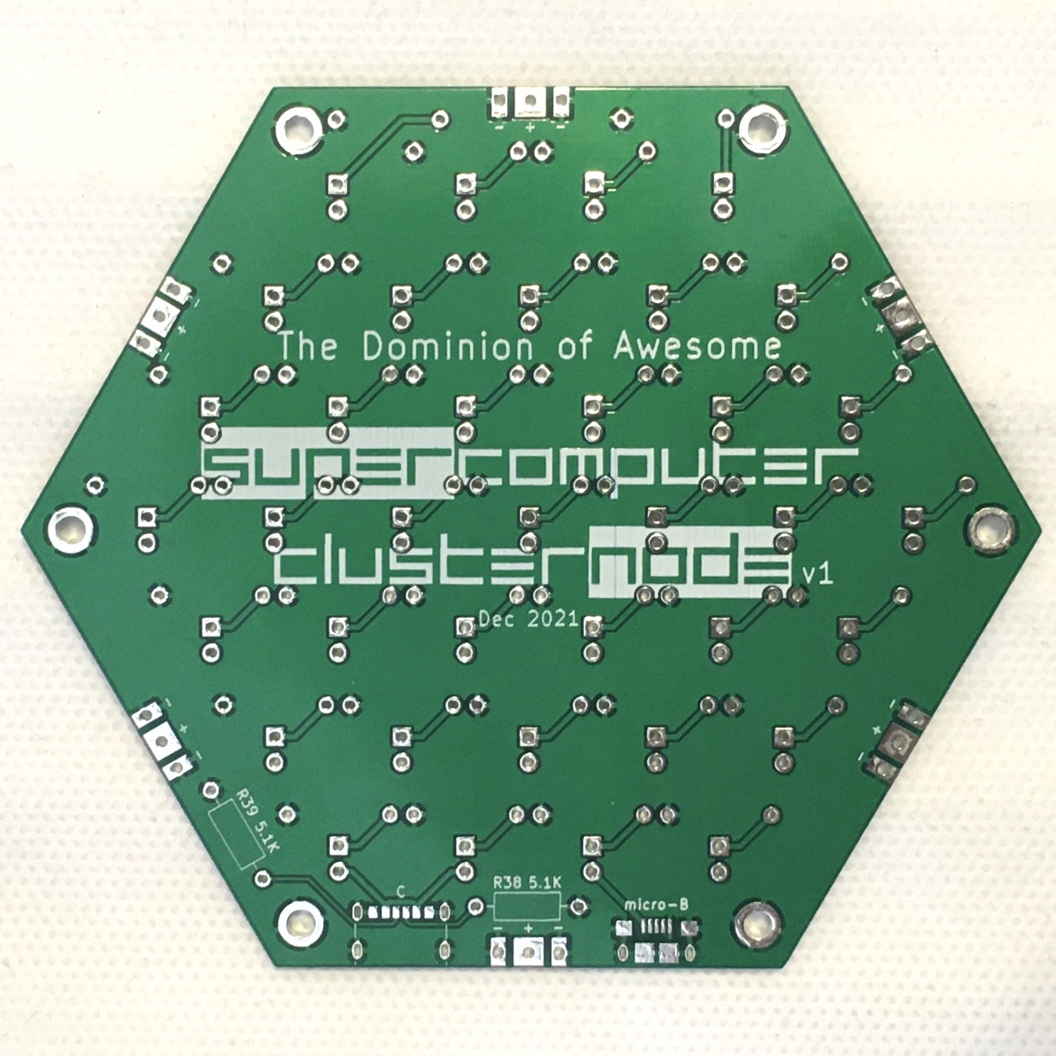
The back of the board has the optional USB connectors and type-C signaling resistors. Both sides have plated mounting holes at the corners and power pads at the edges. The mounting holes are 5mm from the corner, about 4.3mm from the edge, and 45mm from the center.
The edge power pads have two GND pads on the sides and one VCC pad in the center (labeled - and +, respectively). In this configuration, two or more boards can be connected edge-to-edge. Additionally, the corner holes are connected to GND in case that's useful.
Theory of Operation
The basic circuit is a simple set of LEDs in series with current limiting 220Ω resistors. Each LED is represented by this simple circuit.

You may recognize this as the same circuit from the LED Tree, and you can read a full description of how that works in its theory of operation.
Hacking
There's not a whole lot to hack on this one. Most of the auxilliary things you could do are fully intended:
- Build a grid of connected boards
- Daisy chain sets of tiled boards with USB-C cables
- Power it from an old cell phone battery connected to the edge pads
- Make a truncated octahedron
The VCC connections use 1mm traces and GND is a full ground plane on the back side, so it should be able to handle a few amps. Maybe about 6-10 boards connected together before it starts getting warm. The UJC-HP-3-SMT is only rated for about 3A, so if you wanted to exceed that you're better off using the edge pads. Send me a picture if you connect so many they catch fire. :)