POWER PAK

The POWER PAK was created as a subset of another project that never got fully off the ground. I had basically zero experience in power electronics, so it was a proving ground for learning about lithium battery charging and switch mode power supplies. And I learned so much from its failures I made a version 2.
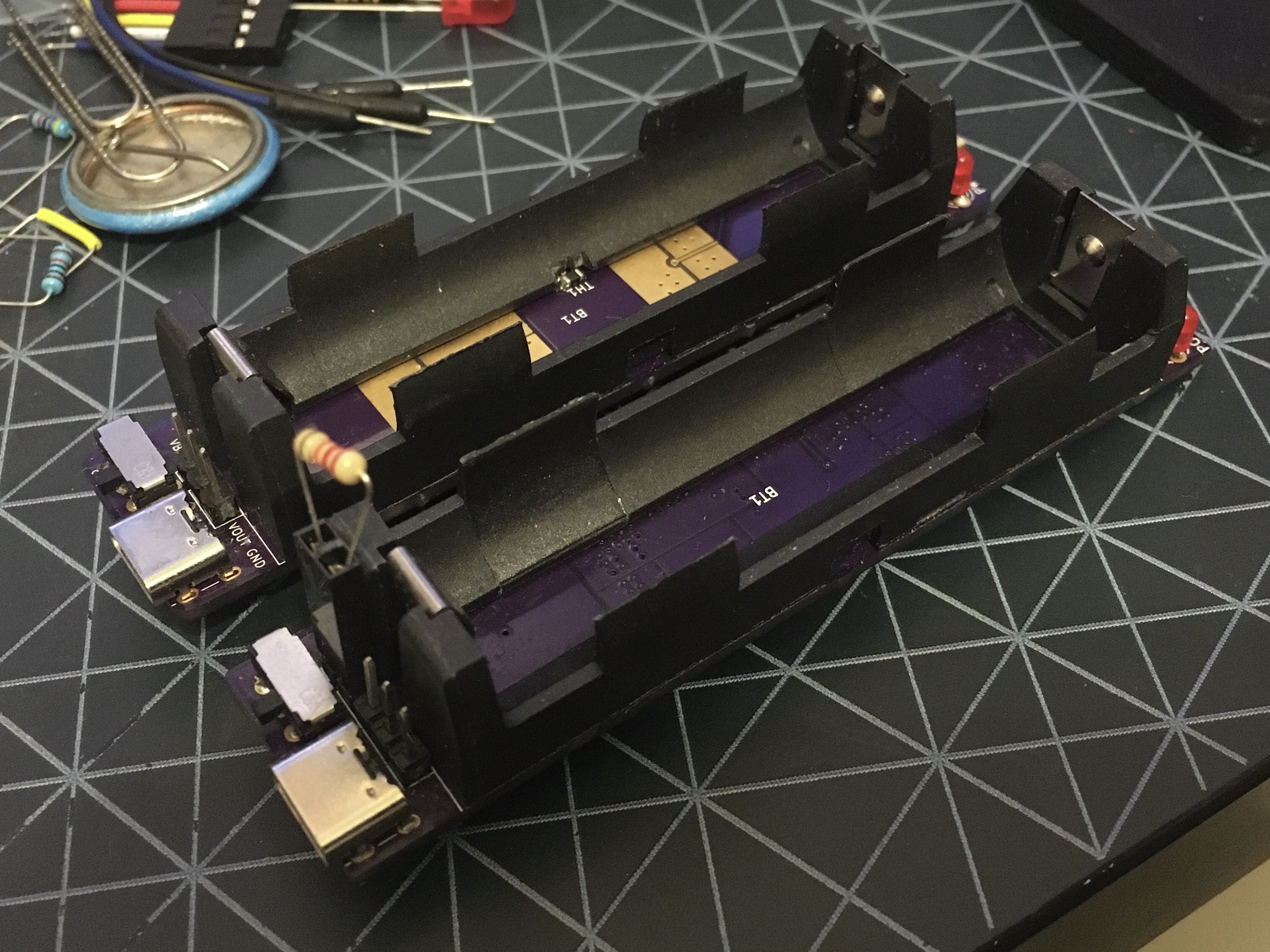
The POWER PAK features two USB ports, one for charging and one for discharing, power and charge indicator LEDs, and a power switch. It uses protected 18650 lithium cells as the board has no over-discharge protection circuitry. It also features several 0.1" headers for more direct connections to VOUT and the battery.
Version 1 used the Microchip MCP73832 linear charge controller and the Microchip (neé Micrel) MIC2288 switch mode boost converter. The charge part worked fine, but I learned a lot about the difference between "switch current" and "load current", and how when the efficiency graph stops at 150mA, that probably means something. It turns out the MIC2288 was completely unable to supply more than a few hundred mA at 5V, and was completely useless for charging phones.
After quite a bit more research, version 2 used the MCP73832's bigger brother, the MCP73834 linear charge controller. It supports faster charge rates and thermal sensing of the battery. For the step-up, I used the Monolithic Power Systems MP3414A, which claimed >90% efficiency between 1mA and 1A. In testing, it was easily able to source more than 1A. It's a boffo little chip. The MCP73834, on the other hand, wound up charging even more slowly than the smaller version, likely due to the absolutely terrible thermal design of my boards. This version is likely safer, though, as it prevents the board from heating the battery as much.
So in the end, there are tradeoffs between each design. The MIC2288 on v1 lacks in supplying current but has a much higher output voltage range (up to 34V). I added a couple of header pins that allow the addition of a bodge resistor to the feedback voltage divider, which allows adjustment of the output voltage upwards. It has been quite useful for breadboard testing (in the images above you can see the resistor added to give 12V output). The MP3414A, on the other hand, is only designed for 5.5V max output voltage so the adjustment headers were omitted. But it actually works for its intended purpose. :)
V1's power diode proved to be an achilles heel. While it was specced for the current, it was only barely specced, and in practice a short on the output will probably cause it to blow up.