OK BOOMER
Table of Contents
Theory of Operation
PWM Audio
The audio output of a Raspberry Pi starts as a PWM signal. The analog value of the signal at that point is represented in the pulse width. If you listened to this directly, it would probably just sound like high pitched noise. If we put a large enough capacitor between this signal and ground, the capacitor will smooth out the signal. And if we put a resistor in series, it will limit the current that can flow in and out of the capacitor. This simple construction is a low-pass filter.

If you pass a PWM signal through a sufficiently restrictive low-pass filter, you effectively get the full voltage multiplied by the average of the PWM on-time. But for this application, we want a middle ground, where it averages out on a short scale, but can still move around at audio frequencies. How do we know what frequencies get cut off by this filter? It's a simple formula.
fC is called the "cutoff frequency", and is the frequency at which the signal is attenuated by 3dB. Frequencies above this will be progressively attenuated as the frequency rises. Don't worry too much about it, the important thing here is we want this cutoff to be above normal audio frequencies.
How do we choose? Usually it works to start with a standard value for one component and solve for the other. The Raspberry Pi folks chose 220Ω and 100nF.
fC = 7234.316 Hz
This gives a cutoff frequency of around 7200Hz. That's not great for audio fidelity! But it works to eliminate high frequency noise.
Here is the portion of the Raspberry Pi schematic that has the audio output circuitry. Curiously, it does not show up in a schematic until the Raspberry Pi 3, though I'm pretty sure it existed before that.
There's a few more parts in the circuit but you can see the RC lowpass filter at the beginning after the buffers. The 100Ω resistor to ground seemed superfluous to me but I left it in my design. The 47uF capacitor afterwards is there for DC blocking. The averaged PWM signal sits at about half the full voltage (3.3V here, so about 1.85V), and what we want is a signal centered around 0V. The capacitor allows current to pass while shifting the voltage to a different level on the other side, provided here by the 1.8KΩ biasing resistor connected to GND.
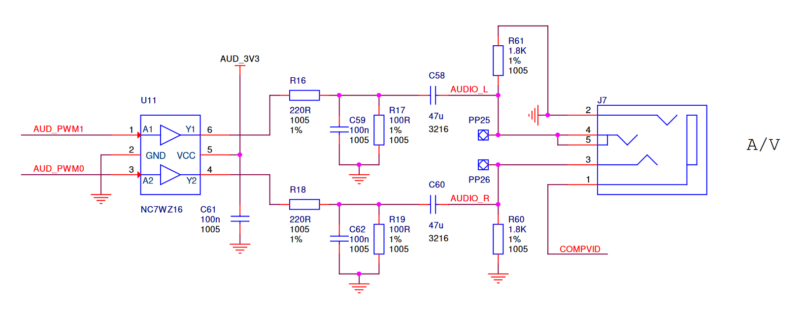
Here's what the circuit looks like in the BOOMER. Why 100nF? Parts consolidation. It made no difference.

And if you're curious, this is what that PWM signal looks like coming out of a Raspberry Pi. You can see that the resolution isn't that great! They mitigate that somewhat by dithering.
Headphone sensing
The OK BOOMER supports simple headphone sensing via a switched jack. When the HP Sense pin goes high, it will cut the output to the speaker and reduce amplification for the headphone output. Here is that part of the circuit:

Ordinarily the LM4875 outputs audio through both Vo1 and Vo2, creating a differential output that drives the speaker coil. Vo1 is also connected to a decoupling capacitor (C3), a biasing resistor (R3), and the switched headphone tip terminal. When no headphone plug is inserted, the sense switch is closed, connecting it to a 100K pull-up resistor (R4) and the HP Sense input. Under normal operation, output on Vo1 will cause some fluctuation at the headphone jack, but since it is decoupled and R3 is a much lower value than R4, it will fluctuate somewhere near ground and shouldn't activate the HP Sense. But when the sense switch is broken, R4 can now fly free, and the HP Sense input will quickly rise to the +5V rail. This activates the headphone output mode.
This does cause a brief loud output in the headphones as they are connected, because the plug can contact the terminals before the switch is broken. Like I said, it's an inexpensive solution.
Raspberry Pi integration
In order to re-route the Raspberry Pi audio outputs to the GPIO pins,
you will have to reconfigure the outputs in config.txt.
dtparam=audio=on
dtoverlay=audremap,pins_18_19
The first line loads the module for PWM audio. It may already be enabled
in your config. The second line re-routes the PWM outputs from their
normal destination (GPIO 40/41, connected to internal audio jack
circuitry) to GPIOs 18 and 19. You can alternatively use pins_12_13 to
connect them to GPIOs 12/13.
Volume
The volume input is a dual purpose control. Between roughly 1V and 4V, it sets the volume. Below 0.3V, it sets the LM4875 into shutdown mode, which turns off the amplifier and reduces power consumption to a minimum. For testing, you can just connect a standard potentiometer divider to this input.
Hacking
There is one soldered jumper on the back of the board that connects the output of the LM4875 to both the left and right channels of the headphone jack. If you cut this jumper, you can wire a second OK BOOMER in as the left channel by soldering between the left side of the jumper (the one with the via hole in it) and the jumper on the second board. I'm not totally sure that the jack sensing works in this mode so it might require further hacking!