Monkey-C
Table of Contents
USB type-C Power signaling
There are six pads on the Monkey-C designed to hold two pull-down or pull-up resistors.
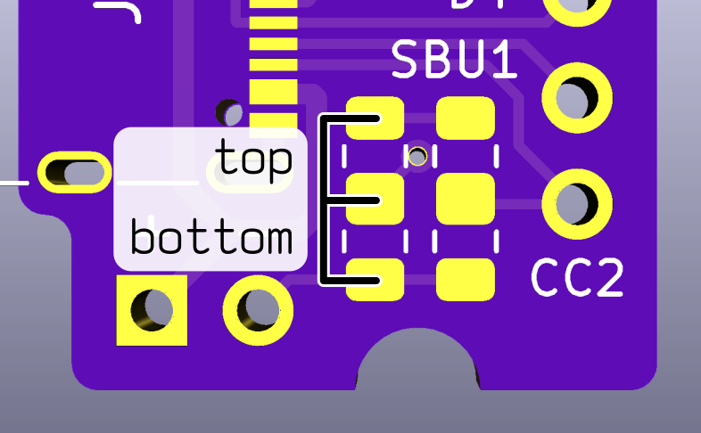
There are two columns of three pads, one for CC1 and one for CC2. The top pad of each column is connected to VCC, and the bottom pad is connected to GND. The middle pad is connected to the CC line. Connect a resistor between the middle and top pads to create a pull-up that signals a power source (charger). Or connect a resistor between the middle and bottom pads to create a pull-down that signals a power sink (device). The value used depends on the direction and current level.
| Direction and current | Resistor value |
|---|---|
| Sink | 5.1KΩ pull-down |
| Source ("default" 500mA) | 56KΩ pull-up |
| Source (1.5A) | 22KΩ pull-up |
| Source (3A) | 10KΩ pull-up |
I definitely don't recommend pulling 3A through a breadboard, but you can certainly try. You need a resistor for both CC1 and CC2 lines and they have to be the same. You can't share a single resistor between them because CC1 and CC2 must remain independent to detect the orientation of the cable.
Build
The main USB connector is the GCT USB4105-GF-A. It comes in several different "stake lengths" (the length of the tabs used to secure the connector to the board). I got the -120 (1.2mm) version but any of them should work.
The resistors are 0805 size, and the headers are plain old 0.1" spacing.