Clock Radio
Power Conversion
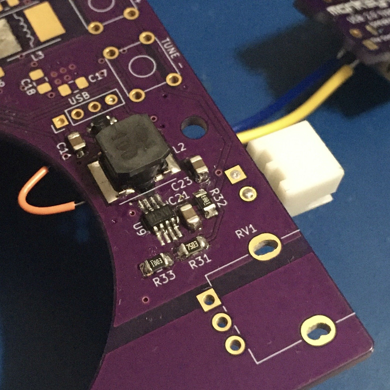
On the flip side of the board is the 5V step up. This is an identical circuit to what I used in the POWER PAK v2. The MP3414A delivers efficiency and way more current capacity than this board needs.
I thought this wasn't working at first, but it turns out if there's any load when the BMS chip starts up, it defaults to overdischarge mode and you have to connect a charger to wake it up.
That kinda makes sense - ordinarily you'd never disconnect the battery from the BMS. And if something did fault between them, you'd want to default to a safe mode.
Anyway, with a little blip of charging at the USB input, it turns on and outputs 5.08V.
I was not so lucky with the 3.3V regulator, a Diodes Inc. DIO6013.
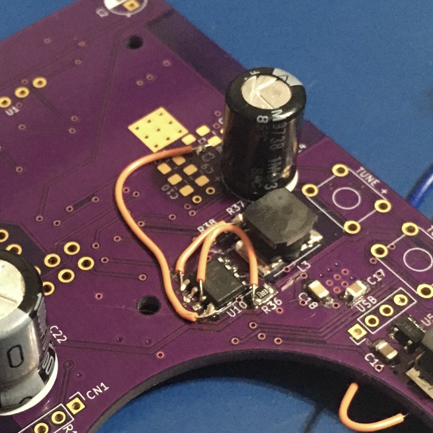
I fat fingered the pinout when building the schematic, so everything on the left side of the chip was reversed. It was recoverable, but slightly annoying to cut traces and bodge in all the wires.
And all of that was working until I put in the capacitors. I think what’s happening now is the BMS is going into overcurrent protection because I didn’t set a resistor correctly. There’s one resistor that needs to be set for that but it was super unclear how to calculate the correct value.
The way it’s designed, once it goes into overcurrent mode, you have to disconnect the load to reset it. There’s no way to do that on this thing.