Clock Radio
MicroSD Jack and Mute Circuit
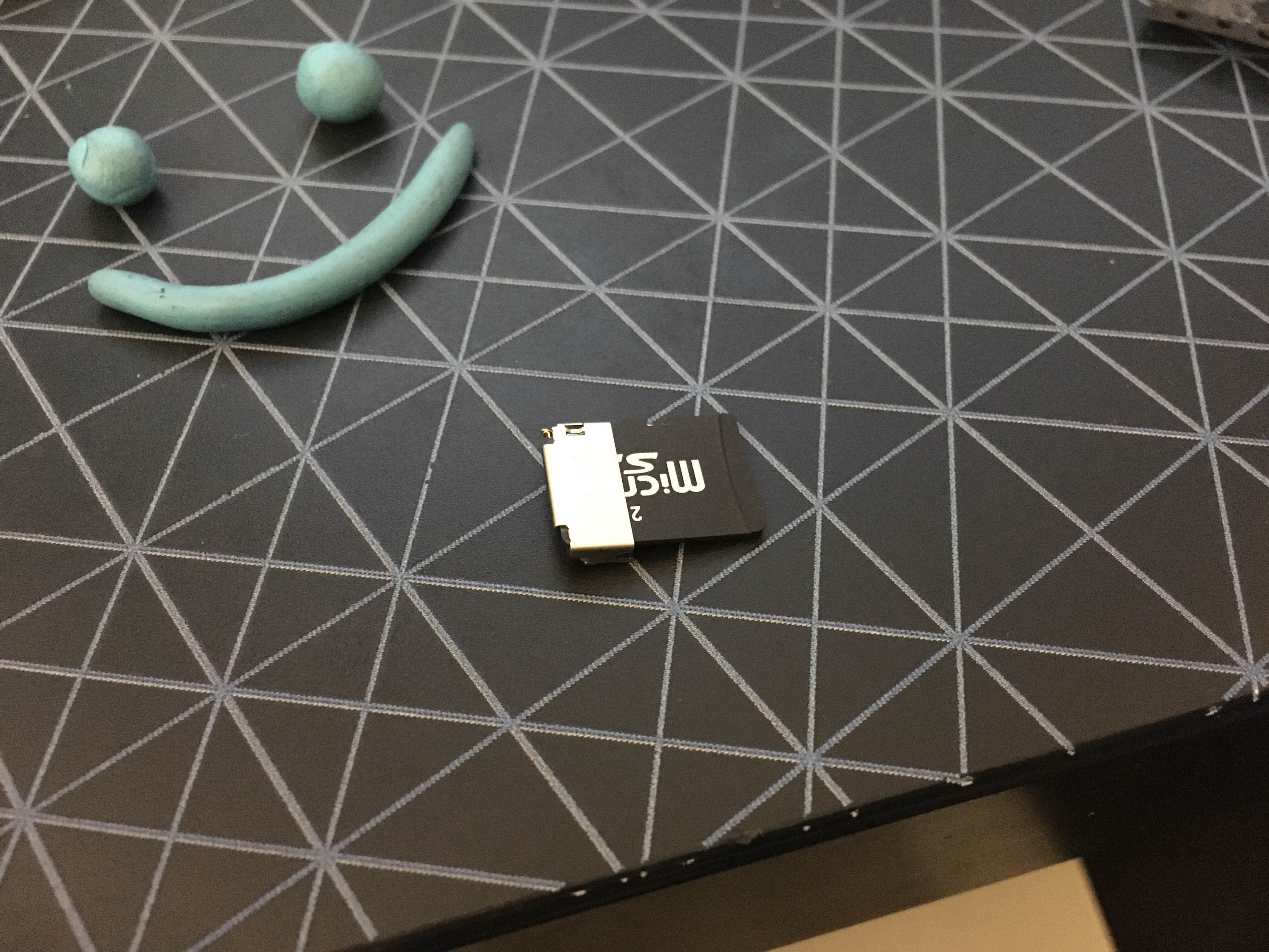
Parts came in. One of the things I wasn't sure about was this micro SD connector. It's a Molex part but the documentation is unclear about how the card detection works. See if you can figure it out.
There's a DET pin and also a POL pin and it turns out it's what I expected. DET and POL are shorted when the card is inserted.
In other news, pop quiz.
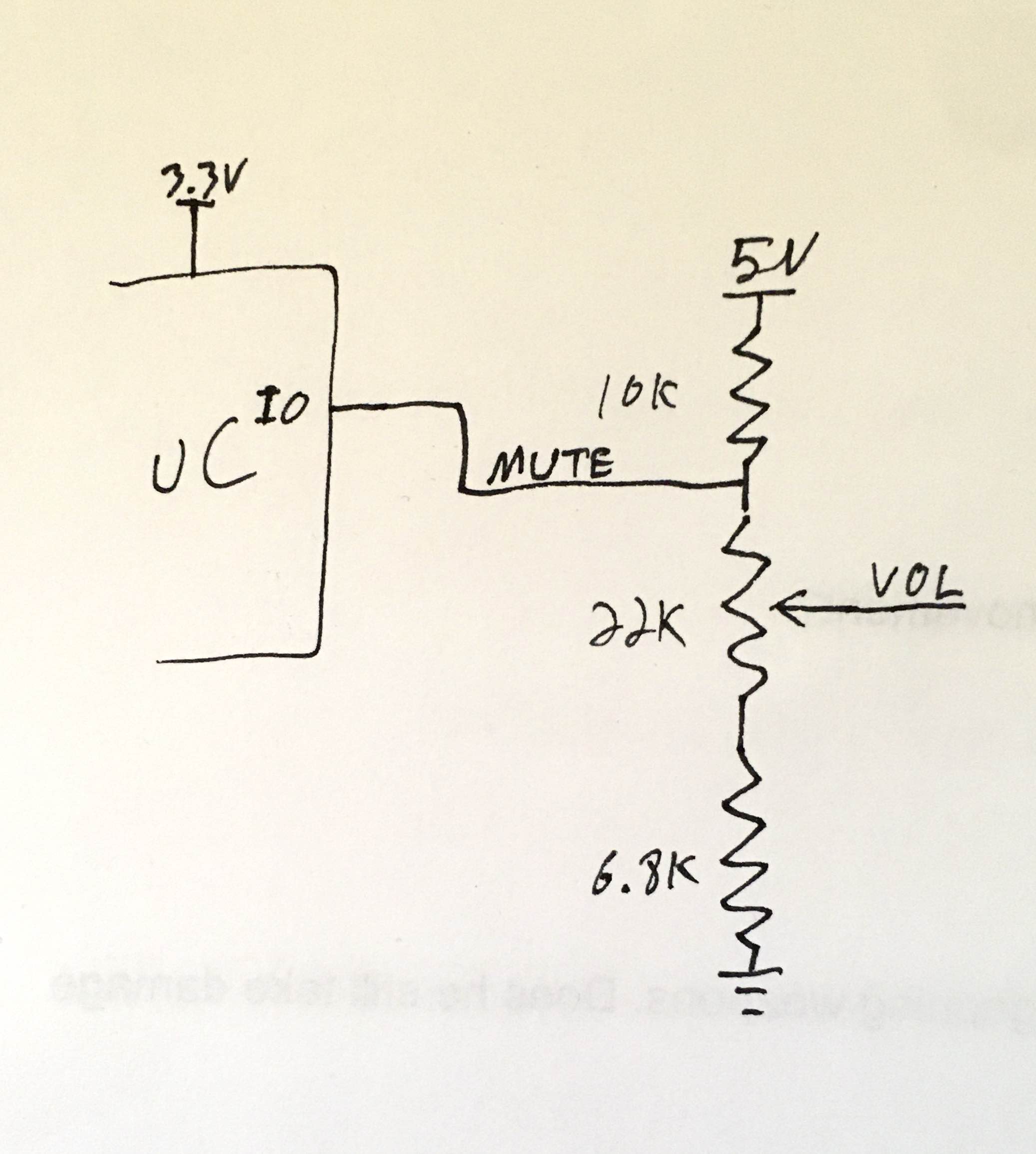
What’s wrong with this mute control circuit? Assume the I/O is only active when outputting low to mute and high impedance otherwise, and assume that the uC is only 3.3V tolerant.
The problem is, when the uC isn’t pulling down the volume, the pin will rest at 3.7V on a 3.3V input.
This probably wouldn’t even break anything. With a 10K resistor between the pin and 5V, it wouldn’t blow the pin or anything. It would just drain a little current through the protection diodes on the uC. But that would pull the mute line closer to 3.3V and screw up the volume calibration.
The purpose of this circuit is to shut down the audio amp. Setting a volume level below 1V puts it into a much lower power mode. So it's less of a mute signal and more of a sleep signal. But the way I did it was kind of dumb because it draws current through that 10K while it's supposed to be saving power. And .5mA ain't nothin.
So the smarter version of this circuit blocks the current at the top of the resistor divider so that VOL is pulled down to ground.
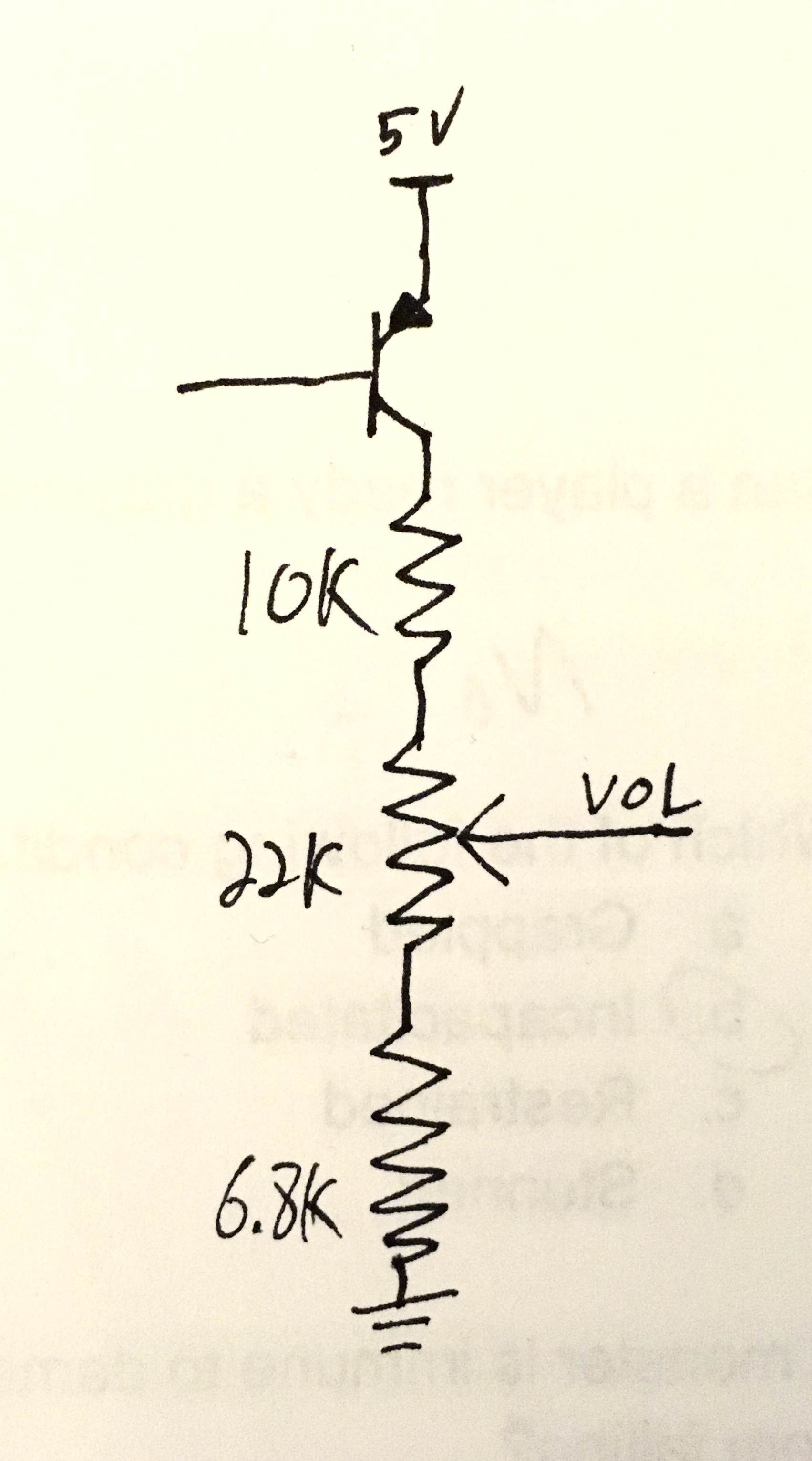
Just a PNP transistor at the top will allow you to turn that whole thing off so it draws zero current.
But this presents a second problem. Your control signal is still only 3.3V. And since a PNP transistor turns on by drawing current out of the base, even a high logic level will turn the transistor on because it's lower than 5V.
So you need another thing in front of that which will shift the control input to this up to 5V. The whole control circuit looks like this:
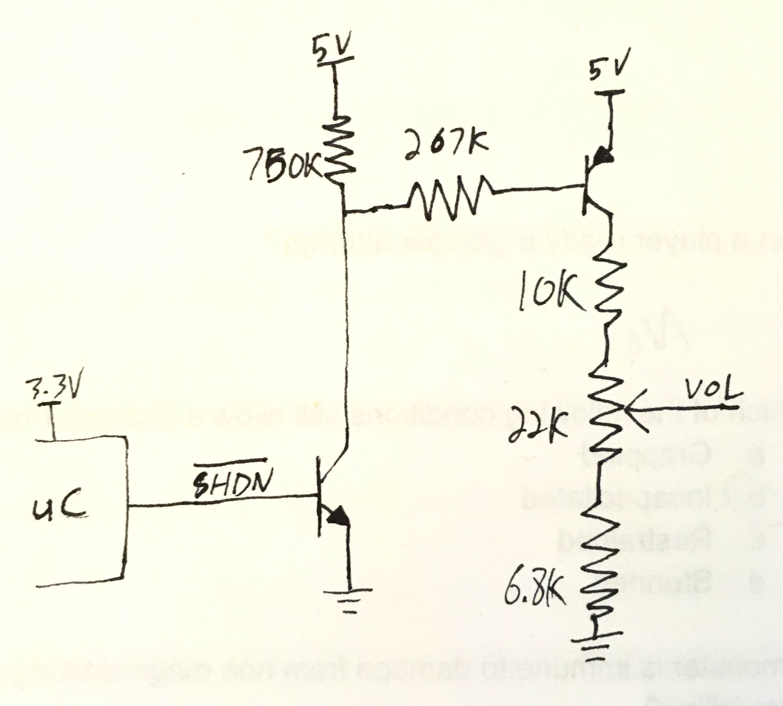
Well there should technically be another resistor between the uC and the NPN transistor, but I'm actually using a MOSFET in my design so I forgot it.
The 750K at the top weakly pulls up the base of the PNP transistor so it's normally off. A high signal from the uC will turn on the NPN, turning on the PNP, which turns on the resistor divider and enables the volume.
Low output on the ~SHDN signal turns it all off with (theoretically) zero current draw.
As a bonus I can use this same circuit to turn off the resistor divider that measures the battery voltage, eliminating that power draw during sleep as well.
(The 750K and 267K seem to be chosen at random but I wanted high values to limit current draw and those were resistor values I already had in my design)
Some experimentation suggests I don't need that 750K pull-up.