Clock Radio
Battery Protection and Charging
Finally got some time to work on building the clock radio board.
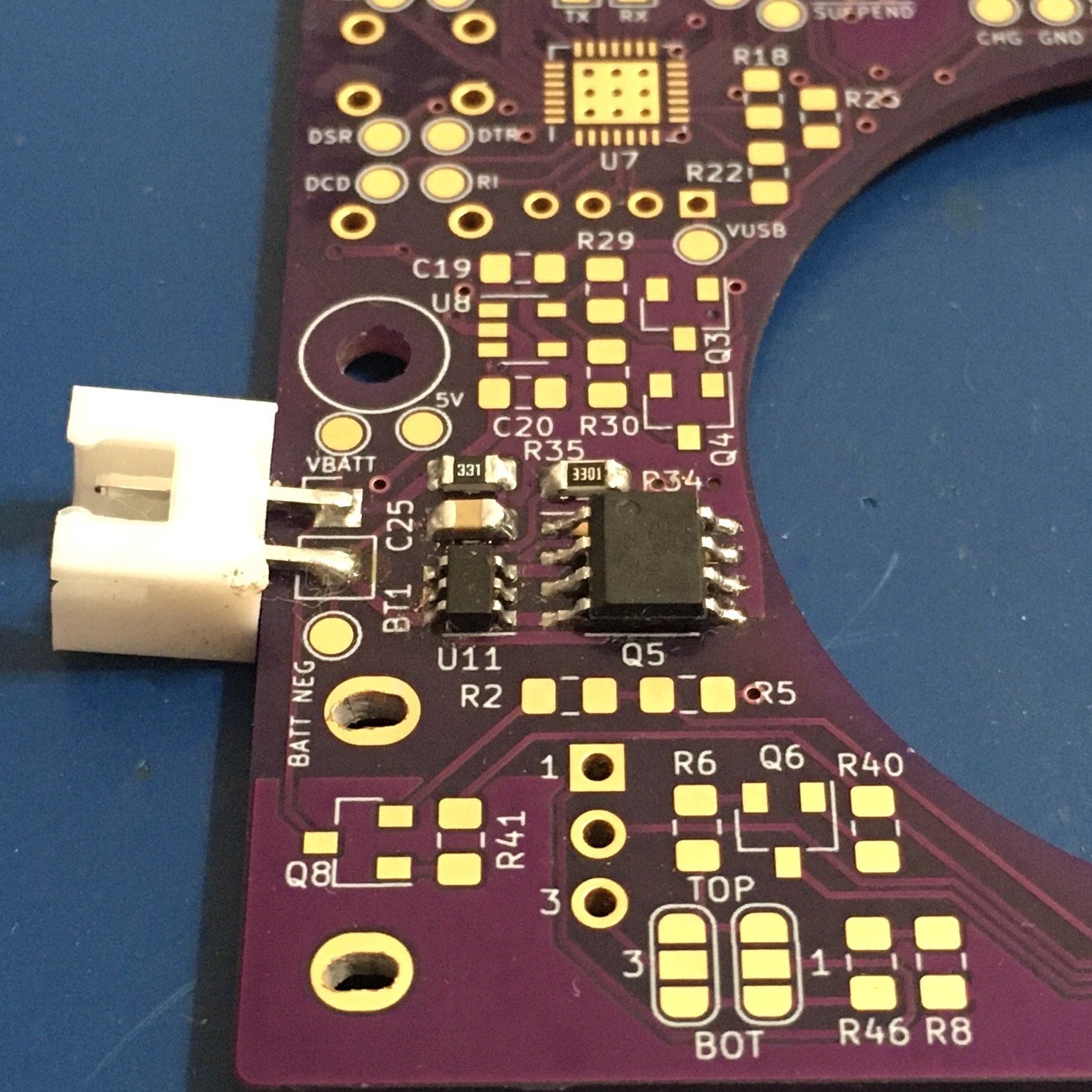
First small step, the battery protection circuit.
Pretty much every battery pack has something like this in it. The six pin chip is the controller, and the big eight-legged one next to it is a dual mosfet. The mosfets are arranged back-to-back so it can control current in both directions. Ordinarily, it allows current to flow freely, so it has little effect on the larger circuit. But for undervoltage, overvoltage, or short circuit, it turns off the mosfets to protect the battery.
I tested that by putting my multimeter in mA mode and shorting the outputs. Passed only about 150uA. I won't be able to test the other parts until I build the rest of the circuit.
You can also see the slots I dremeled out because I checked hole positions on the potentiometer but didn't check their size.
Next stop: battery charging.
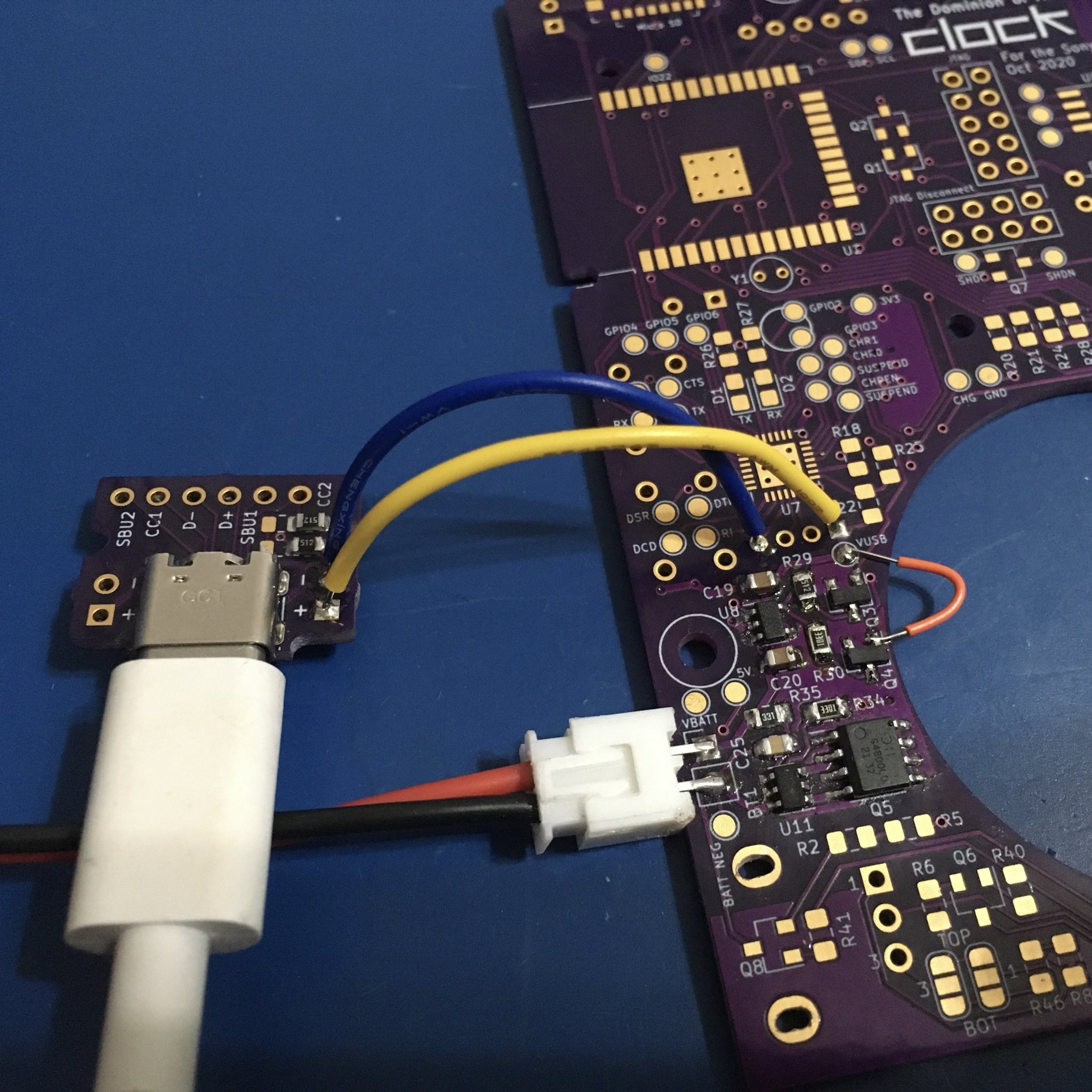
Battery charging circuit is in, and appears to work. I’ve bodged in the USB connector and a charge enable signal. On a CP2101N you get charge control signals but since I don’t have one I’m just enabling the switching mosfet directly.
On to the power conversion. First, up to 5V, then down to 3.3.