Clock Radio
Battery Test Fit
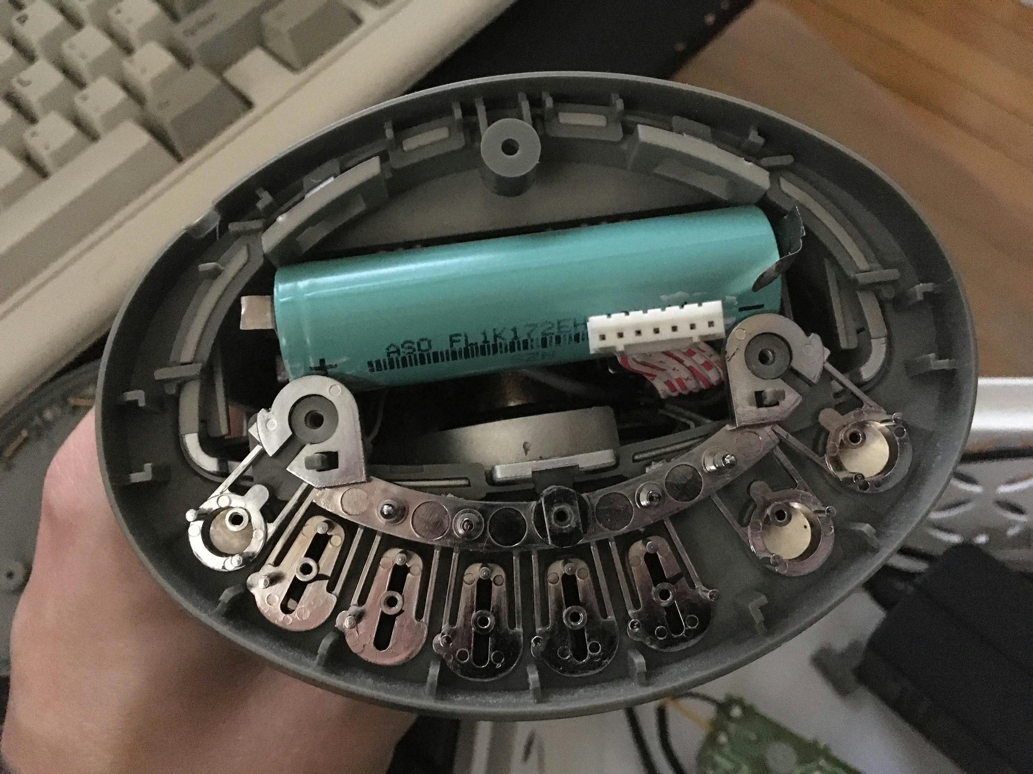
Doing some test fitting. It seems like there’s baaaaaarely enough room to fit an 18650 where the radio coil used to go.
I had originally planned on putting it in the back curve of the device, but there’s barely enough room there too. But also I tested my prototype with the existing speaker and it’s craaaaaaap. So if I want to mount a bigger speaker, I need that space.
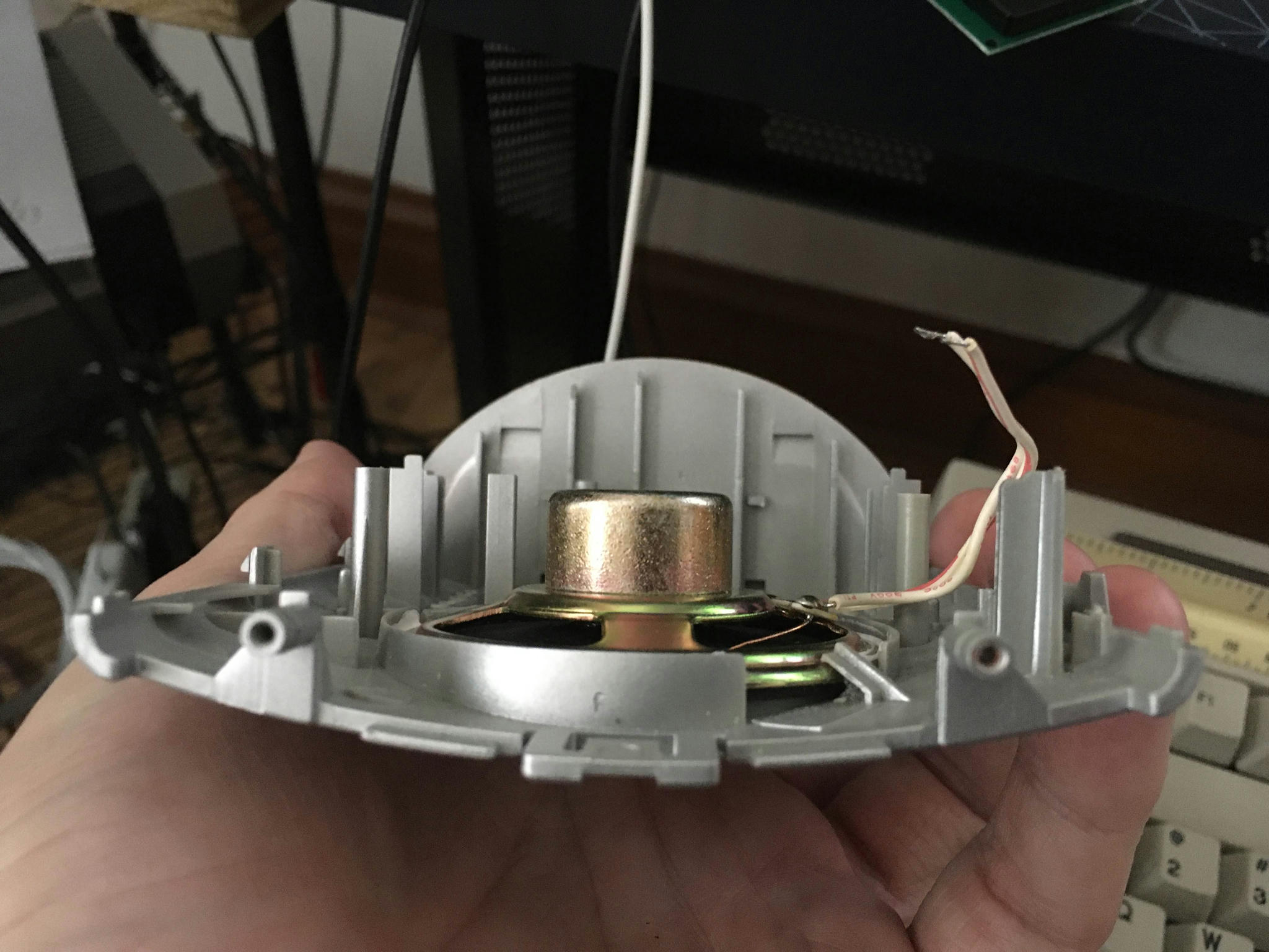
I wonder if that may have been the original intent of this chassis design, since it’s ideally shaped for a big cone speaker.
You can see that the speaker goes right up to the board level, but there’s plenty of room between there and the back curve of the case.
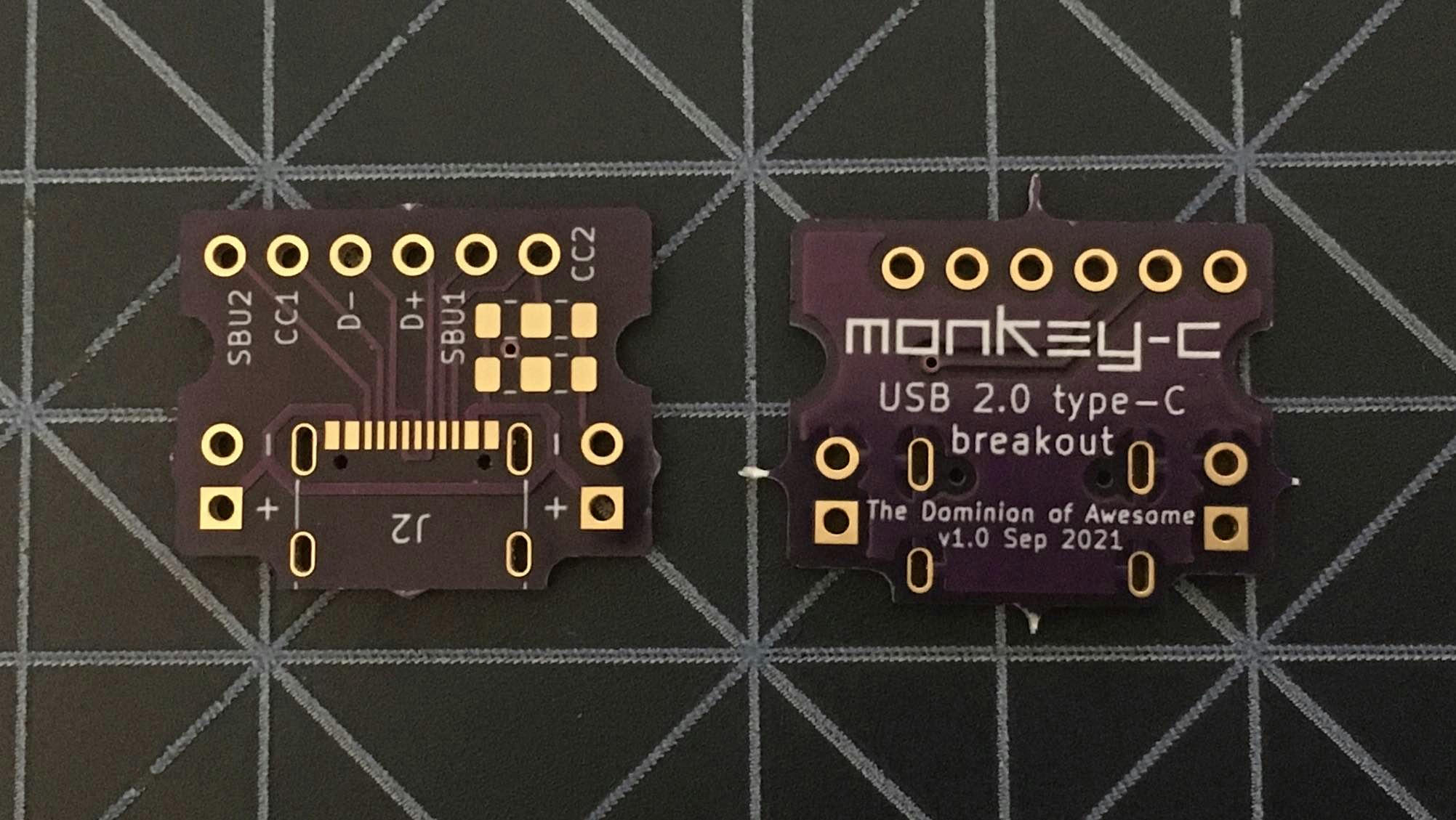
I also had these made. Just a tiny USB 2.0 type C breakout board. It’s designed to fit in the power rails and rows of a breadboard, but it can also be used to easily add a USB jack to any project (as I’ll be doing with the clock radio).
“2.0 type C” sounds weird but the fun (?) thing about USB standards is the physical layer and data layer are separate. You can choose to only support a subset of the type C connector. My XZ1 Compact does this too. It’s type C but only supports USB 2.0. No HDMI alternate mode or anything.
And that means there's few enough pins you can hand solder the jack. Not easily mind you, but it’s possible.


