Clock Radio
Analog Filtering
So let's talkg about ANALOG FILTERING and how I fucked this up.
There's two important concepts at play here. Capacitive coupling and op amp voltage ranges.
Capacitors are charge storage devices. And most often they're used exactly as that, storing a voltage with reference to ground. For power decoupling and RC timing, they just store and release.
But they have another important property — they pass current. The two plates of a capacitor want to stay at the same voltage potential. That's why they will discharge when a current path is provided. But if neither plate is held to a voltage reference, current flowing into one side will, through electrostatic action, cause current to flow out the other side to equalize this potential. There is a limit, of course, as only so much charge can be accumulated. But they will operate like wires before they saturate with charge.
This is a really useful property for building AC filtering circuits. It means you can couple the current between sections of a circuit without coupling the voltage. In the steady state, a capacitor will gain or lose charge, but if the signal is oscillating and the capacitor is big enough that its level of charge doesn't change significantly at the oscillating frequency, it will simply act as a bridge to push current between their respective steady state voltage levels.
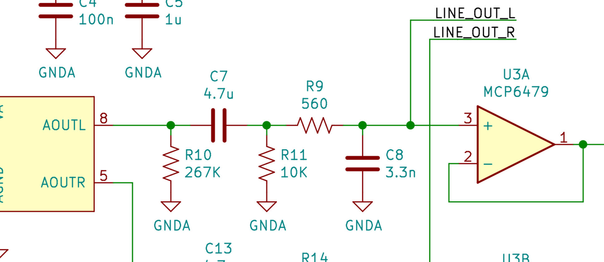
That's the function of C7 in this circuit. The DAC on the left operates between 5V and ground, and outputs an AC voltage centered around 2.3V. As that current passes through C7, the signal is shifted to center around the steady state voltage of the next filtering stage. And what is the steady state voltage of that filtering stage? That is controlled by R11, which is connected to ground.
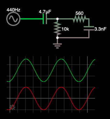
This is what happens. And this was the desired effect of the circuit, because I copied it out of the CS4334 evaluation board schematic. But this is a problem for me because you can see at the other end, it's connected into an op amp.
Op Amps are magical devices that can do analog math on signals. But they have their limits. Namely, they have an upper and lower voltage input that defines the limit of their operational range. Often you'll see an op amp design that requires a negative voltage input because the signal is centered around ground. But I'm just using +5V and ground to supply these, so the only range the op amp can work with is between 5V and ground.
I think you might see the problem at this point.
Because the input signal is going below ground, the op amp clips any part of the input that does that.
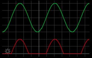
My fundamental misunderstanding here was the purpose of the evaulation board schematic. Its purpose was to provide a ground-centered audio output with a high pass filter. But I need my signal to remain between 0 and 5V for the next stage, so I shot myself in the foot.
This is technically fixable, with some compromises. I can just bridge across C7 and remove R11. That will fix the DC offset but it will mean my line outputs will have a DC offset. That's fine as long as it's battery powered or if it's on an isolated power supply. As soon as this and the receiving device share a ground reference that will Cause ProblemsTM.
Technically the other way this could be fixed is by referencing this filtering stage to 2.5V instead of ground. But that's more work since I already have a properly biased signal coming in.
I could also move the capacitor between the filtering and the line out jack, but that's going to be tricky since there's no good place for it. That would more or less require soldering to scraped away traces.
If I were making a few of these I'd make a new board revision with fixes, but for a single device it's hard to justify.
Aside: Technically the voltage inputs are the bounds of what is possible, not the exact limits. Many op amps cannot work with signals close to their voltage rails and may only operate within a margin of a volt or two of those rails. The ones I'm using are "rail-to-rail", meaning they support inputs and outputs along the entire voltage range.
Some newer op amps can do "over the top", meaning that they can support input voltages outside of the voltage rails but the output is still limited.
Some common op amps, like the LM358/LM324, can support input and output down to the lower rail but the upper limit is about 1.5V below the positive rail. Those are useful for doing low-side current sensing or amplifying very small DC signal voltages.