Clock Radio
Testing 3D Printed Screw Holes
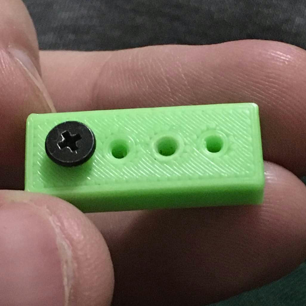
Doing some test prints to see how accurate screwholes are.
I was expecting they’d be too big but it works the other way around. It bleeds inward so you have to oversize the holes. From the right, this is 2, 2.1, 2.2, and the screw is in 2.3mm. It’s an M2 screw, which has a nominal outer thread diameter of 2mm.
You can see where I jammed it into the 2.1mm hole and it just made the hole bigger. Anything is a self tapping screw if you put enough force behind it.
But it seems like maybe the slicer isn’t taking the nozzle width into consideration. Or maybe it just settles that imprecisely.
Note from the future: This was an error in measuring the size of the screw, see this later post.
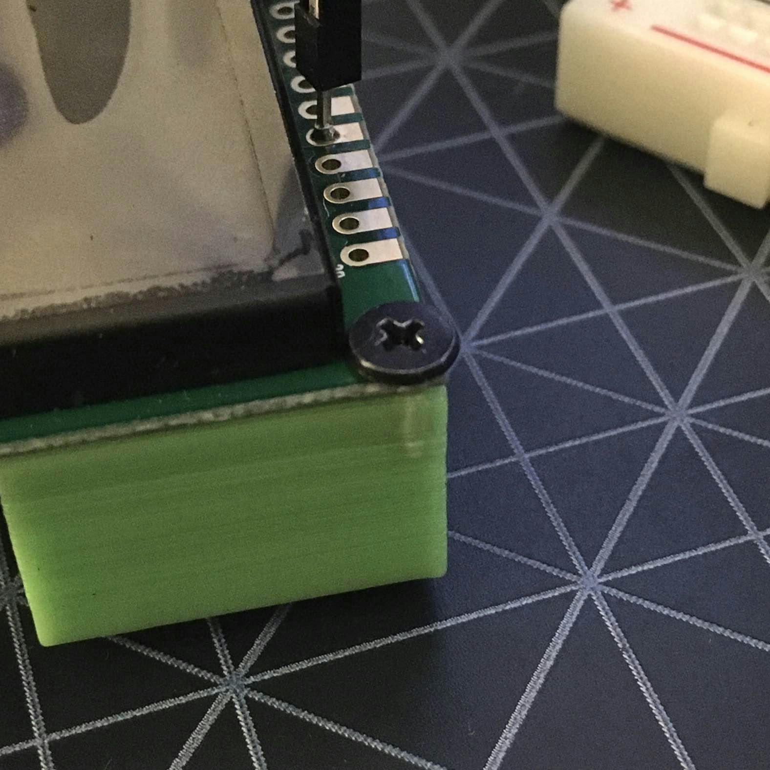
Anyway, the holes were for mounting the OLED screen in the clock radio. Seems like it needs a little more meat on it.
It's basically a 2mm wall around the edge and I'm also learning that this is exactly why brims were invented. It pulled away at all corners.
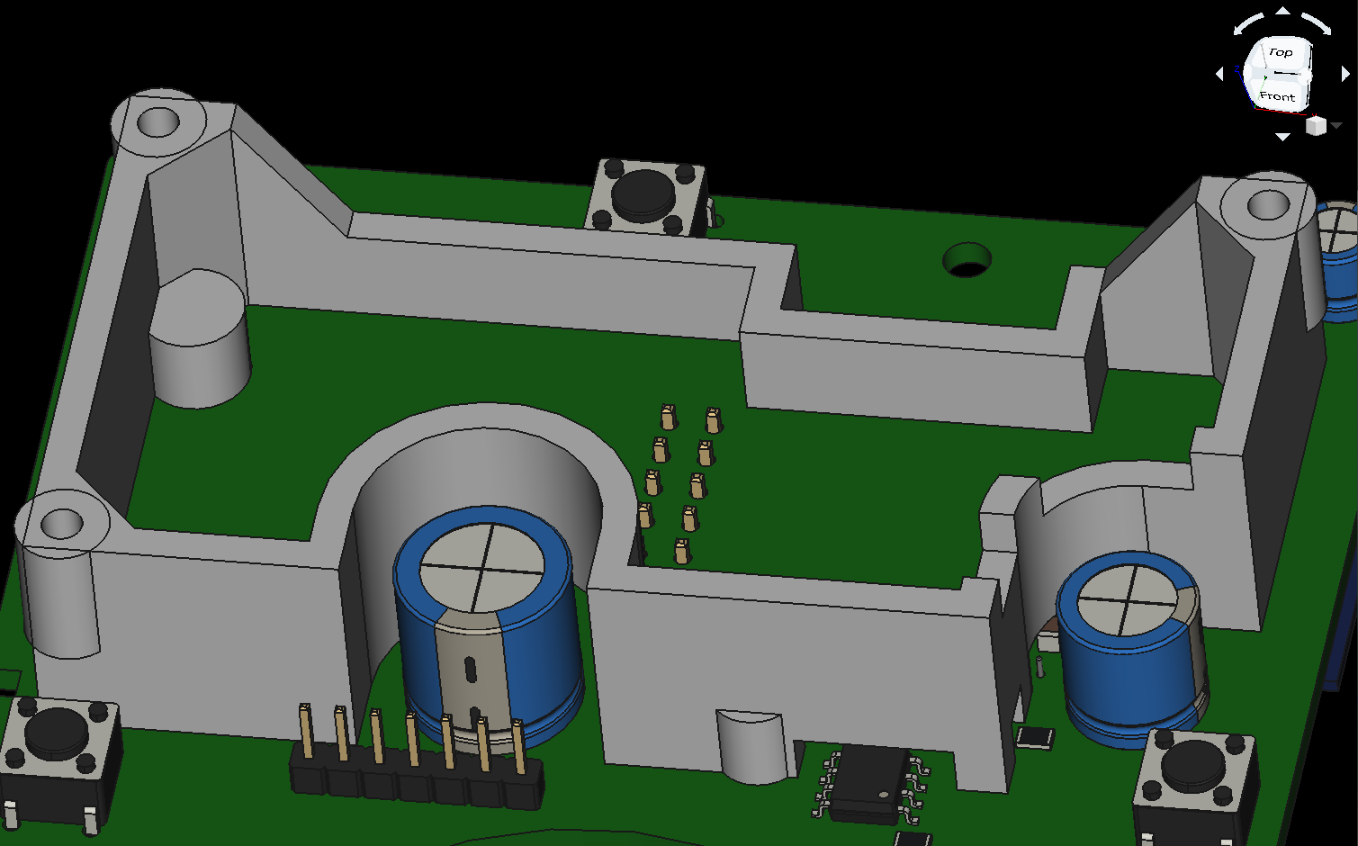
One of the cool things you can do with KiCad is export a 3D model of the board with components. It's pretty slick for validating a design that goes with it.


