CC SINK
Table of Contents
Theory of Operation
A constant current load differs from a simple resistive load in that it always pulls a set amount of current regardless of the input voltage. While you can use a big beefy potentiometer to dissipate a few watts, using a MOSFET allows heatsinking, allowing much greater loads. A constant current is also useful for measurement, since it eliminates one of the variables in calculating power. This is useful when you use a current sink to measure things like battery capacity.
So how do you control the current? Basically, through the magic of operational amplifiers. Op-amps are worthy of a whole other dissertation (and Dave Jones can explain it pretty well), but the basic rule is that the output of an op-amp will change in a way that minimizes the difference between the + and - input terminals. It will move the output upwards if the - terminal is below the +, and downwards vice versa.
The basic circuit looks like this:

Let's start by considering the current going through the MOSFET. Since some amount of current C is being passed, the same amount of current must be going through R4 and into ground. Because of Ohm's Law, we know that the voltage across R4 is 1Ω * C = C. So the - terminal of the op-amp sees a varying voltage proportional to the current.
The + terminal is connected to a resistor divider composed of a 10K resistor and a 10K potentiometer. Let's assume VCC is 5V (because as you'll see later, this is a USB-powered device). This divides the 5V and the voltage range seen at the wiper varies between 0 and 2.5V.
We know the op-amp will adjust its output to try to get its - and + terminals to meet. So what happens? Let's suppose we've set the potentiometer so that the + terminal is 1V. If we start with no current flowing, the - terminal will be at 0V. So the op-amp starts increasing the voltage on its output. This will proceed until the MOSFET turns on and starts passing enough current to make R4 rise to 1V. At that point, the - and + terminals are at the same voltage, the op-amp stabilizes and we are sinking exactly 1A. Likewise if we decrease the potentiometer output, the op-amp will lower the output to meet the new set value. Whatever voltage we set at the + terminal results in that amount of current being sinked to ground.
The magic of the op-amp is that it doesn't need to understand the gate threshold voltage or the response curve of the MOSFET to do this. It just adjusts itself to meet whatever conditions are given to it. It is a simple analog computer.
The full circuit adds a few more components to improve stability of the op amp. It also uses the extra op-amp to buffer the current sense output. This may add an offset to the measurement at very low currents, depending on the characteristics of your op-amp. You can always measure current directly across the resistors, but watch that the measurement device doesn't draw enough current to upset the measurement.
Board Design and Assembly
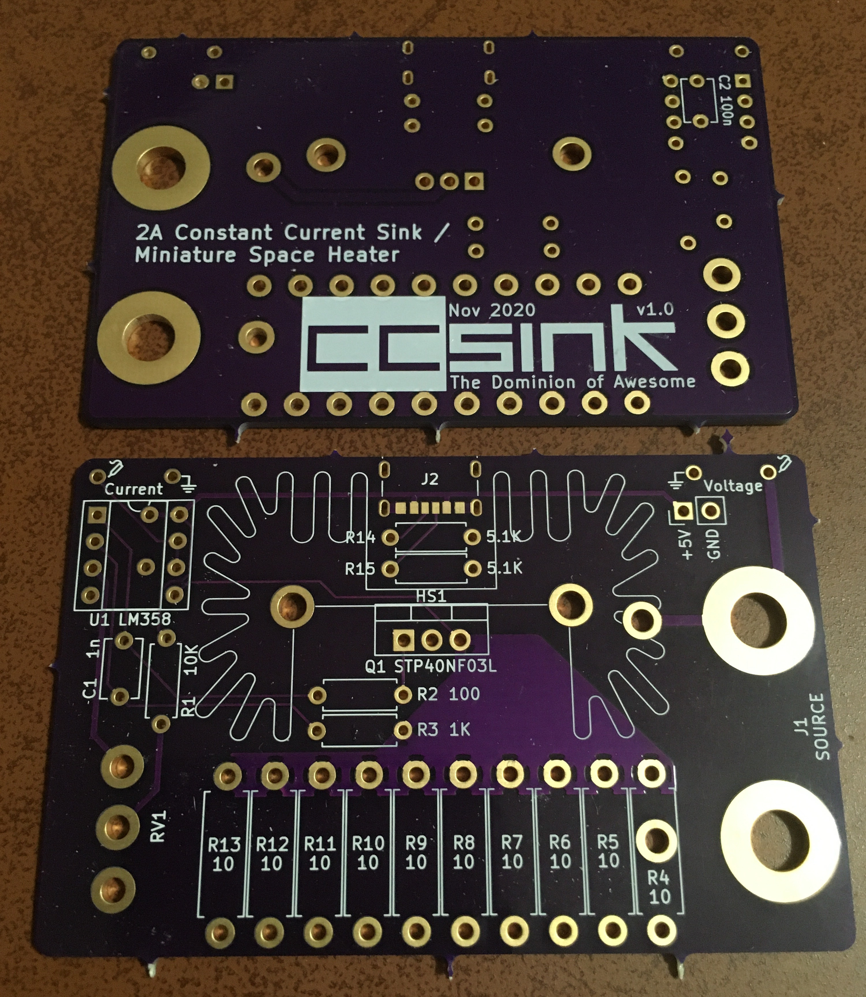
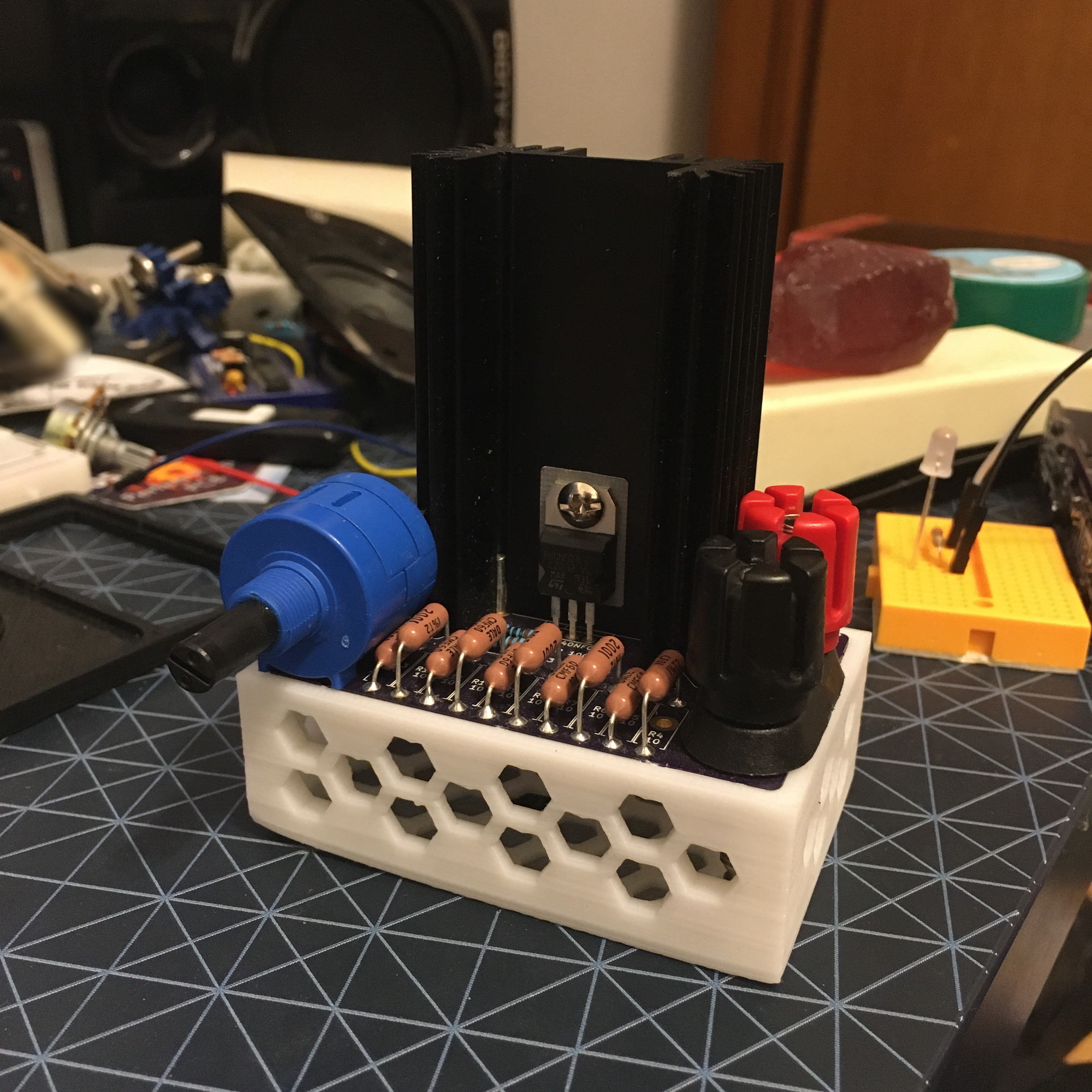
The board design is... compact. It crams everything into a small area that leaves a lot of things hanging over the edge, like the input banana plug terminals and the potentiometer. It also doesn't provide any mounting holes or room for feet and the length of the terminal posts means it doesn't sit level. Because of this, I created a 3D printable stand that makes it a little nicer to work with.
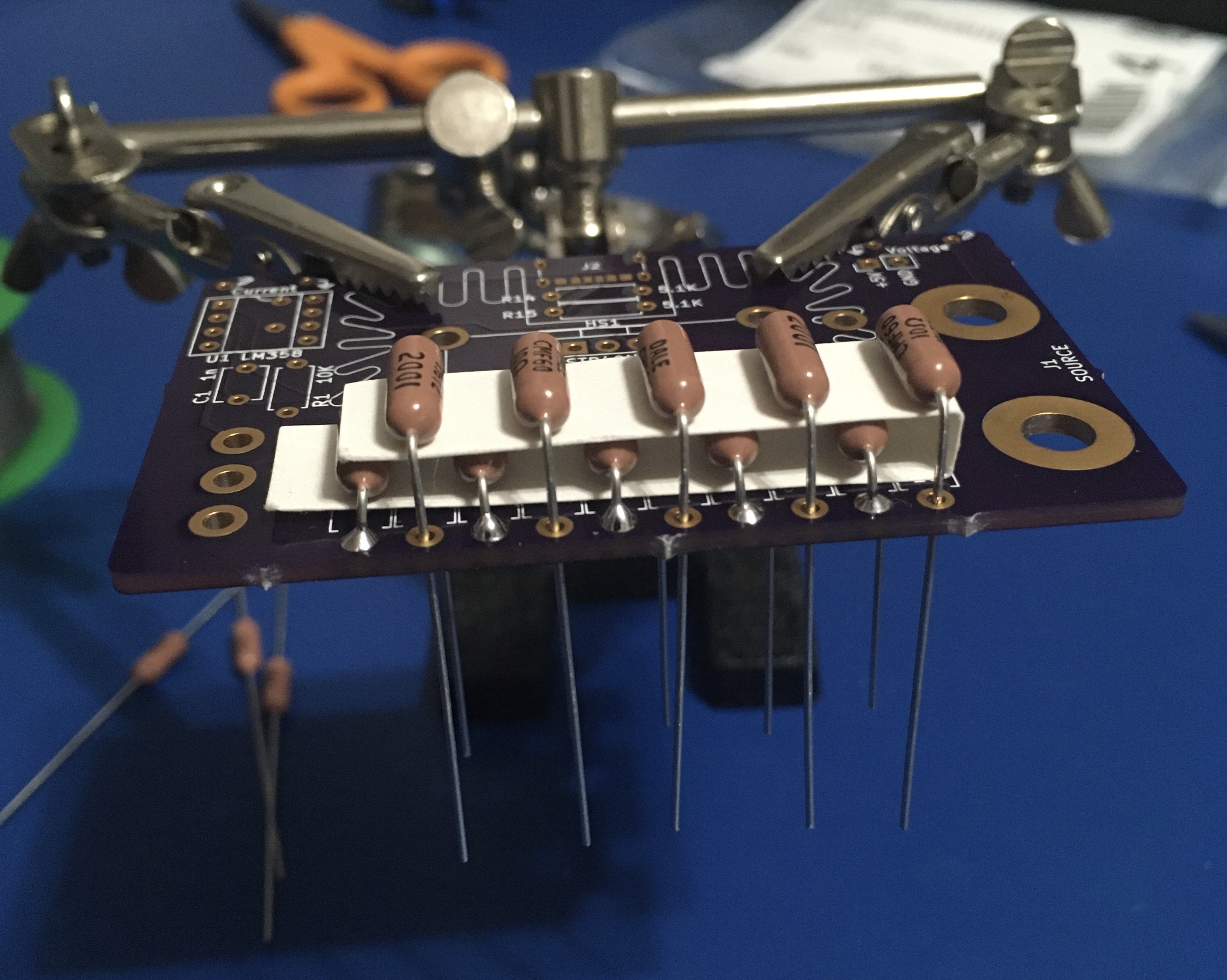
While assembling the resistors, I liked the idea of a staggered arrangement for better heat dissipation. I used a small strip of card stock to space them.
I also used a sil-pad for better thermal contact between the MOSFET and the heatsink. You could also just use regular thermal paste.
Parts
Load sense resistor(s)
Instead of a single 1Ω resistor, I used ten 10Ω 1W resistors. This spreads the load out and averages their accuracy. At 2.5A, each resistor dissipates about 625mW so if higher current handling matters to you, you should select resistors with a higher power rating.
You can make the CC SINK work with smaller ranges by increasing the resistance. A 10Ω resistor, for example, will sink 0-100mA with a 0-1V input. Likewise, a smaller resistance can sink larger loads. But beware the power ratings and heat sinking! You may also need a different MOSFET or op-amp. See below.
MOSFET
Any old MOSFET will do as long as it has a gate threshold within the output range of the op-amp and it can handle the voltage and current you expect to pass through it. Most larger "logic level" MOSFETs will work here. The one I used in mine was a STP40NF03L. I got a bunch of them for cheap because they're EOL. Since I'm mostly testing 5-12V power supplies, its modest 30V rating is fine. And 40A is way more than enough.
Op-amp
The important specification for this application is the op-amp's input and output voltage range. Because we're sensing a voltage near ground, we want the input range to include 0V. Not all op-amps will do this! It's also important that the upper limit includes the voltage level corresponding to the maximum current you want to sense. In my design, I only wanted to go up to 2.5A, so I've used the boggest of bog standard op-amps, the LM358. The LM358's upper limit is specified as V+ - 1.5V, or 3.5V from a 5V supply. So that works fine.
The output range should include a high enough voltage that it will turn on your MOSFET enough to achieve the current you want. (I recommend staring at your MOSFET's output characteristics curves until they make sense) The LM358's output range is typically 0V to about 3.6V when it's not driving a significant amount of current. This works fine for the STP40NF03L, and it should be fine for most logic level MOSFETS. If you really want the extra range for driving a less sensitive MOSFET or just for driving it to higher currents with higher voltages, rail-to-rail op-amps like the MCP6002 are readily available.
Potentiometer
I chose to buy a wire wound 10-turn potentiometer so that I could get fine accuracy. They are pricey, though! You can equivalently use a standard single-turn if that fits your budget/parts bin, or if you just don't need a ton of accuracy. I used the Bourns 3590P-1-103L.
Binding Posts
I used the Pomona 6883 dual binding post, but you can find generic ones in the same style for cheaper, or use single posts. There are also auxiliary terminals if you just want to connect some wires. Don't skimp here if you plan on using the binding posts a lot, though. There is a noticeable quality difference.
Heatsink
The MOSFET will be dissipating pretty significant power once you start moving beyond a few hundred mA. Definitely don't try this circuit without a heatsink beyond that point. Extruded and stamped aluminum heatsinks can be found all over the place and even a small one will help a lot. There's certainly a limit, but generally, bigger is better. The one used in this board's design is the Ohmite RA-T2X-64E.
Operation
The CC SINK is typically powered by 5V from the USB connector. This powers the op-amp, which provides the gate voltage for the MOSFET. Depending on the op-amp, it's entirely possible to use a different power source as long as it provides sufficient headroom to turn on the MOSFET and is below the maximum voltage rating of the op-amp (the LM358 tolerates up to 32V).
The sink input voltage is limited only by the voltage rating on the MOSFET, and can be higher or lower than the source powering the rest of the circuit.
Sense Outputs
There are two pairs of through-hole terminals on the rear of the board. Each pair includes a ground terminal and are designed to be used with probes that have a ground springs (like you'd find on an oscilloscope). The one on the left outputs a voltage level based on the current. For the standard 1Ω sense resistor, it outputs 1V for 1A. The pair on the right is connected directly to the binding posts and simply reports the voltage. With these two measurements, you can determine exactly how much power is being dissipated by the CC SINK.
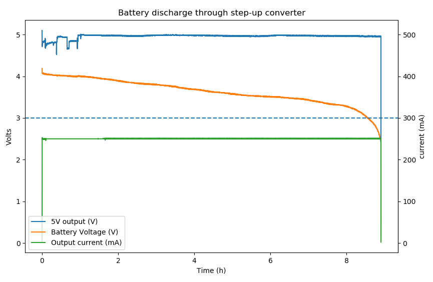
If you have a logging multimeter or oscilloscope, you can log current and voltage over time to determine the discharge characteristics of a battery source. For example, here is a test I ran on the POWER PAK v1, measuring the output voltage and current, as well as the input battery voltage. I tested with 250mA current and stopped the test when the output turned off.
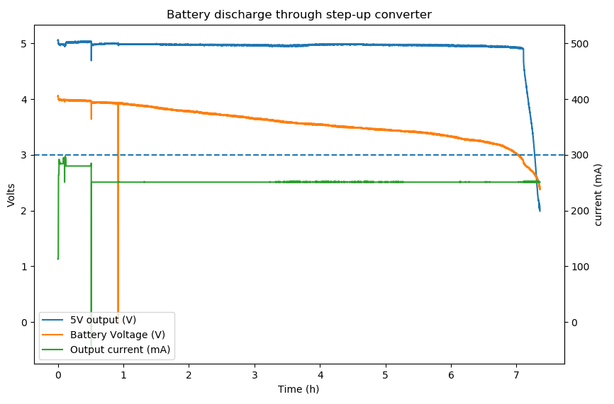
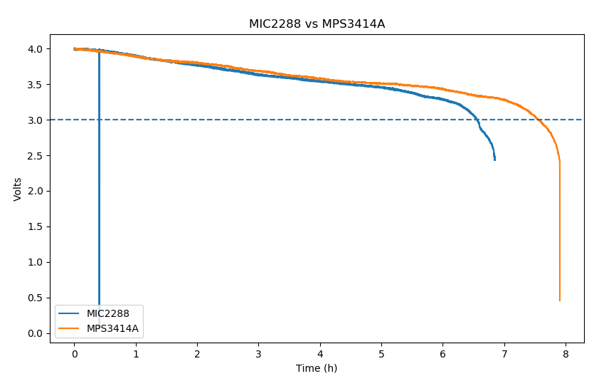
Interestingly, there wasn't a hard cut-off after the battery got low. Here is the same test on the POWER PAK v2.
Comparing the battery discharge curves directly shows the improved efficiency of the MP3414A.
Hacking
It may be tempting to power the CC SINK from the load under test, but the control circuitry will draw some current and skew your results.
As mentioned in the Parts section, there is a lot of versatility on how much voltage and current this can handle, as well as the testing range. As designed, it can dissipate 12.5W from a 5V source. It wouldn't be hard to increase that, but beware that all that energy turns into heat. That's why the silkscreen calls it a "Miniature Space Heater". It's worth putting a temperature probe on the MOSFET to see how hot it really gets.