Toxoplasma Gondii
Table of Contents
This manual describes version 1 of the Toxoplasma Gondii board.
Overview
Toxoplasma Gondii is a recreation of the circuitry inside an Amiga mouse (at least according to this schematic). It receives raw signals from optical sensors and filters them through a comparator to produce clean digital quadrature signals expected by the Amiga.
Theory of Operation
Most ball mice are implemented with two quadrature motion trackers. These are typically slotted wheels which block the light of an LED shining on two photosensors. As the wheel moves, the sensors are shaded and lit in sequence. This allows relative motion to be detected.
PC mice sense this motion and encode it into some kind of serial stream of motion reports. Amiga mice are simpler, though - they just report the motion signals directly over the pre-existing joystick interface1.
The sensors are usually phototransistors connected to a resistor. When light is not shining on them, the resistor pulls up the output to VCC. When light is shining on them, they pull the output down towards GND. In this way, the movement of the wheel creates a varying analog voltage relative to the position of the wheel. This analog voltage is compared against a reference voltage created by a voltage divider. This turns the analog signal into a digital signal.
This does not implement everything you need to run the mouse. It assumes that the LEDs and photosensors will be driven by circuitry already inside the mouse. It also does no processing on mouse button signals. Making a mouse work properly might require some hacking outside the scope of this manual.
Build
Board Description
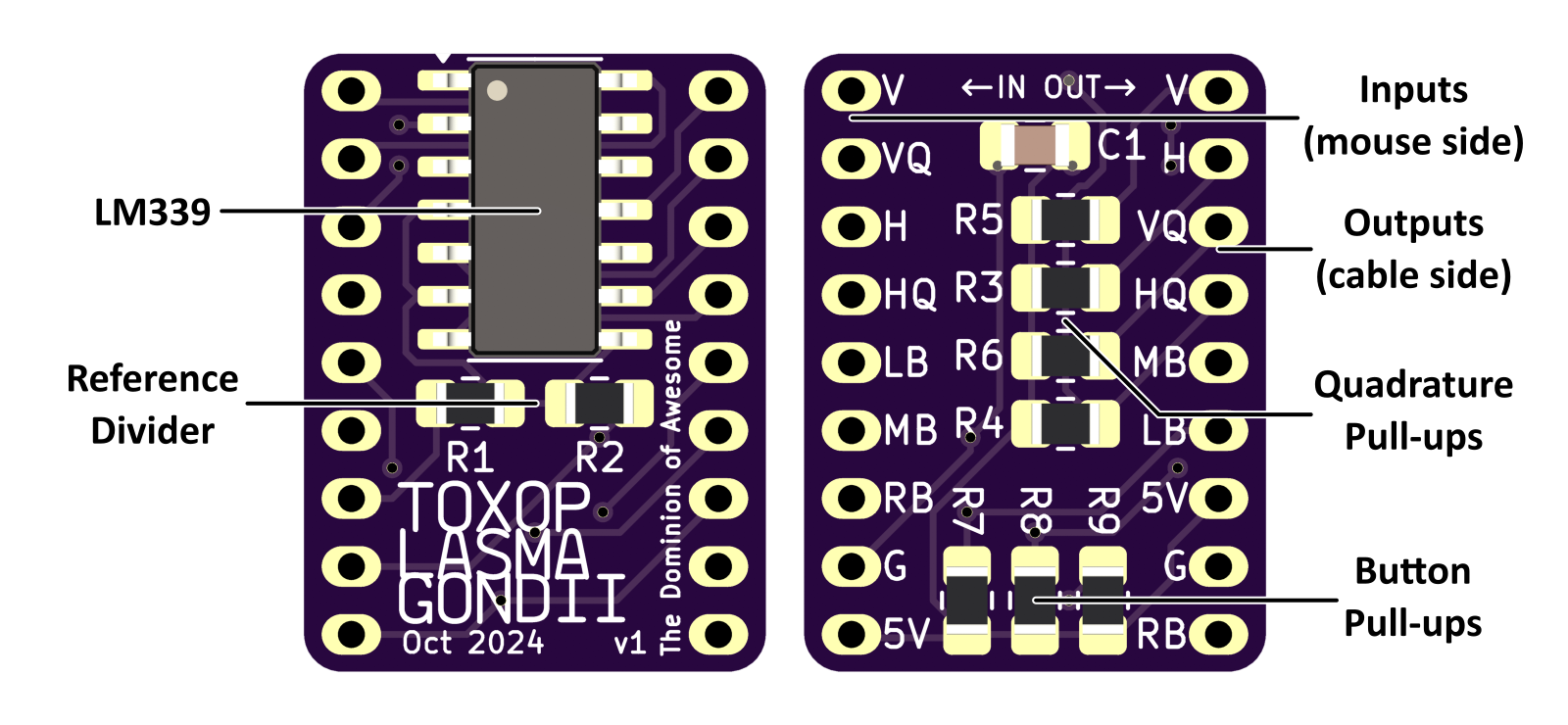
The board is fairly simple, only having three types of components. There is the LM339, its decoupling capacitor, and a series of resistors for the pull-ups and reference voltage.
Reference Divider
The reference voltage will depend on the levels you see from the sensor circuits. I configured mine with 10KΩ resistors for a voltage level of 2.5V and that seemed to work great. I did have to adjust the LEDs current to make that work well on my mouse. YMMV.
Pull-Ups
The pull-ups on the Toxoplasma board are only for the outputs to the computer. There is no filtering on the mouse buttons. They are connected directly from input to output, and they assume that the switches in the mouse are connected active-low (that is, they connect to ground when on). You may not need to add pull-ups on the Toxoplasma board in this case. But they are there if you need them.
Headers
The input and output headers are 2mm pitch, which might be useful for JST PH connectors or the like. The outputs are in the same order as an amiga mouse/joystick connector, with V on pin 1 and right mouse button on pin 9. The inputs are not in any particular order, but the quadrature signals, mouse buttons, and power connectors are grouped together.
Which signal is which on the quadrature inputs will change the direction the mouse cursor moves. If you find the cursor going the wrong direction, swap the regular and Q output for that axis and it should fix it.
