Spite Sprite
Table of Contents
This manual describes version 2 of the Spite Sprite board.
Overview
The Spite Sprite is more or less an implementation of the reference schematic in the AD724 datasheet. It supports the PAL/NTSC and FSC/4FSC options via solder jumpers. It runs from the 5V provided by the Amiga, and produces both composite video and S-Video simultaneously.
Operation
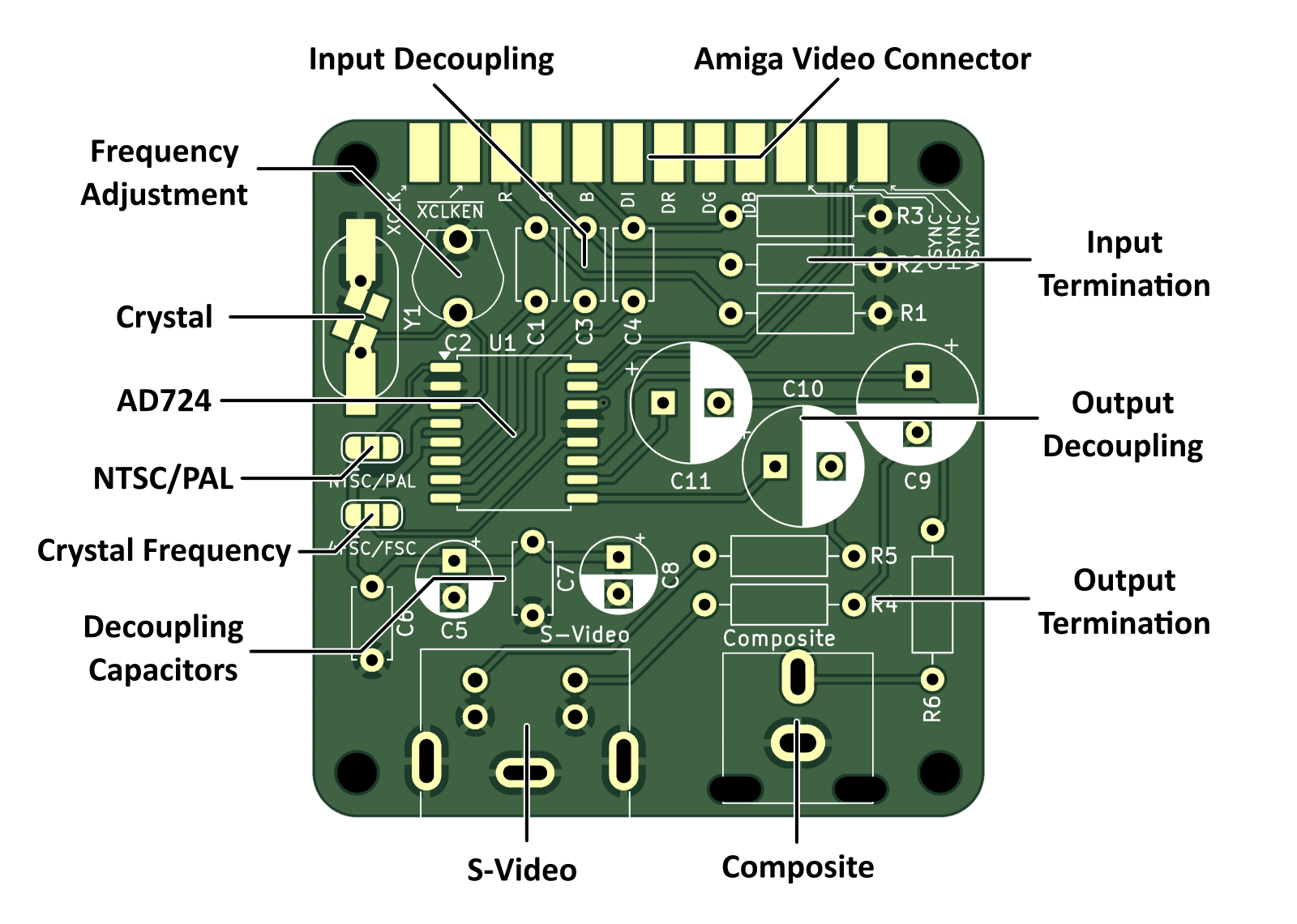
The Spite Sprite is plug-and-play. It should produce video immediately after power-on. When using composite output, you should tweak C2 to fine tune the color frequency. This can fix some shimmering or crawling artifacts. It does not really affect the S-Video output.
The device does support 50Hz video with NTSC color, which is very useful for running PAL programs on an NTSC machine. It might also support 60Hz with PAL color, but this has not been tested.
NOTE: The Spite Sprite is not a scan rate conversion device. It only accepts TV scanrate input, and will not convert 31.5Khz VGA signals to 15.7KHz TV signals.
Build
Board Description
The board should be built as a 1.2 or 1.4mm board so that it can fit between the solder cups of the D-sub connector. If you have standard solder tail/board mount termination on your connector, you can probably use a 1.6mm board.
All of the video connector pads are plated and labeled even though they are not all used. This may be useful for hacking in an external clock or accessing the 12V line or some other thing.
Connectors and Other Parts
As you can't get 23-pin D-sub connectors anymore (well, as of writing some specialty Amiga shops have them but they won't be around forever), I fashioned one by cutting down a DB-25 connector (see the gallery). I have since learned that there are 3D printed solutions which may work as well. I used a connector with solder cups (the kind that would normally be used for hand-made wire-to-plug applications) so that the board would fit snugly between the solder ends.
I think any 4-pin mini-DIN jack should work for S-Video, as they all have compatible pinouts to the CUI MD-40SM I used.
For the composite jack, I used a CUI RCJ-044. Anything in the 04X series should work, but 044 is the yellow one. I don't know if there are compatible connectors from other manufacturers.
Build Options
The board offers two jumpers to configure the video standard and crystal frequency. The NTSC/PAL jumper configures the AD724 for the appropriate color encoding. It must be matched with the appropriate crystal frequency. The FSC/4FSC jumper allows the color frequency to either be the normal color frequency or 4x that frequency. The appropriate frequencies for these options are listed below.
| Standard | FSC/4FSC | Frequency |
|---|---|---|
| NTSC | FSC | 3.579545 Mhz |
| PAL | FSC | 4.433620 Mhz |
| NTSC | 4FSC | 14.31818 Mhz |
| PAL | 4FSC | 17.73448 Mhz |
The crystal footprint itself supports three options - classic HC49 cans with leads, SMD HC49 cans, and 3.2x2.5mm SMD cans. If your HC49 part has a metal bottom, I recommend taping over the smaller SMD pads or otherwise making sure the can doesn't contact the board.
Omitting S-Video or Composite
If you only want one of the two outputs, you can omit a number of parts.
To omit composite video, you can get rid of the output decoupling capacitor C11, the output termination resistor R6, and of course the jack itself. You can also probably omit the color frequency tuning capacitor C2, but you may need to replace it with a 10pF capacitor for stability (I haven't tested this).
To omit S-Video, you can get rid of C9 and C10, R4 and R5, and the S-Video jack.
