LED Tree
Table of Contents
The LED Tree is a simple 16 LED module that optionally supports simple digital control via 74HC595 shift registers. It supports USB type-C and micro-B power sources and both power and data can be daisy-chained through standard 0.1" headers.
Care and Feeding
Each LED is connected to the board via a twisted pair of solid core wires, which can be bent into whatever shape you desire.
The red wire in each pair is the positive terminal and the black is the negative. The long leg of a LED is the anode and it connects to the positive terminal. The short leg is the cathode and connects to the negative terminal. If you plug in a LED backwards, it won't damage it, it simply won't light up. Just turn it around and it'll be fine (probably — if you significantly exceed 5V they may be damaged by reverse breakdown).
Each LED is an independent circuit, and it's perfectly fine to connect and disconnect LEDs while the circuit is powered on. The epoxy molded lights can also be run through the dishwasher as long as you take care to keep them contained. Just make sure they're dry before you plug them back in. :)
Specs
- Input Voltage: 3-6V DC
- Total LED Power Consumption: 0.72-1.28W (144-256mA at 5V)
- Per-LED Power Consumption: 45-80mW (9-16mA at 5V)
The Board
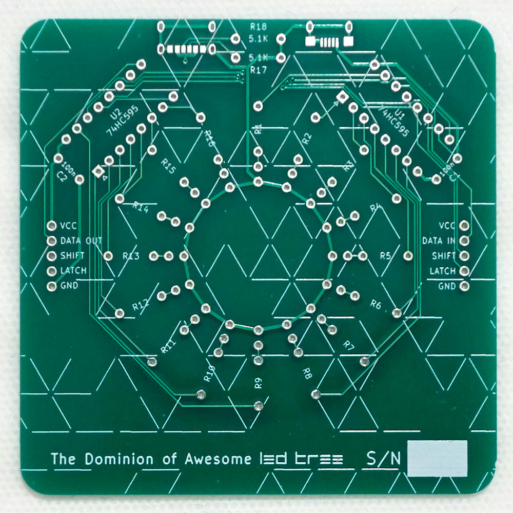
On the front of the board are most of the components and connectors. At the top are two footprints for USB type-C (left) and micro-B (right) connectors. In between them are R17 and R18, 5.1KΩ current sense resistors for USB type-C. They're optional, but including them allows intelligent devices to properly recognize the device as a power sink (but other options are possible — see Power Options below).
Below the USB ports, flanking either side of the top are components U1 and U2, two 74HC595 shift registers, allowing digital control (see Digital Control and Adding Digital Control Components below). Pin 1 is the square pin with the triangle pointing towards it. Next to each of them are C1 and C2, non-polarized 100nF decoupling capacitors.
Radiating outward from the center of the board are holes for the LED wires and current limiting resistors R1-R16. Current flows from the outside towards the inside meaning that the black wires connect to the innermost ring of holes and the red wires connect to the hole just outside those. The resistors follow outside of those. The resistor holes are somewhat close together (only 0.4") so you may have some trouble with thick-leaded resistors (I did).
On the left and right of the board are the daisy-chain connectors, designed for standard 0.1" (2.54mm) pin headers. The pins are, from top to bottom, VCC, DATA IN/OUT, SHIFT, LATCH, and GND. DATA IN connects to the SER input of the right 74HC595. DATA OUT connects to the QH' output of the left 74HC595.
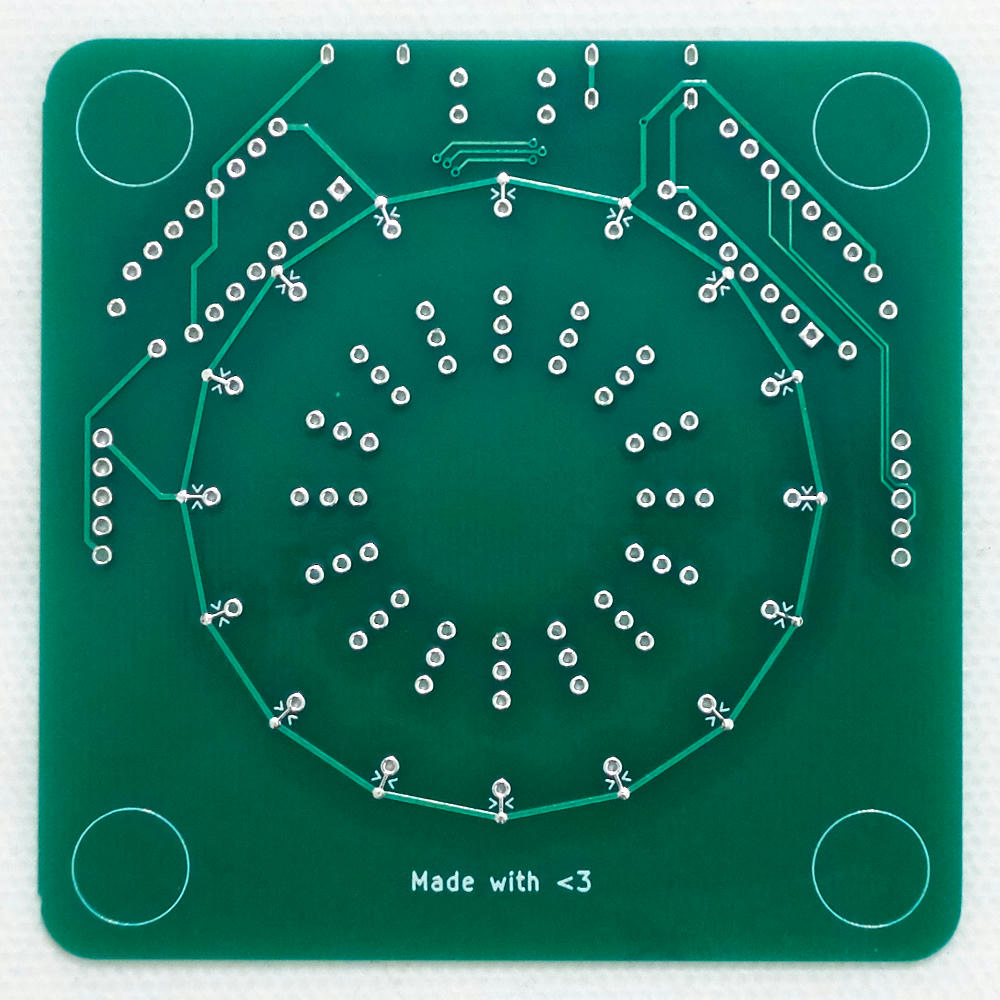
The back of the board has no components of its own, but it does mark the jumpers that must be cut to enable digital control. These jumpers are between the 16 sets of two inward-pointing chevrons (again, see Adding Digital Control Components).
Theory of Operation
The basic circuit is a simple set of LEDs in series with current limiting 220Ω resistors. Each LED is represented by this simple circuit.
Why do you need current-limiting resistors? The short answer is LEDs will burn out with a moderate amount of current — for your typical indicator LED, perhaps somewhere around 20-40mA. The more complicated answer is that LEDs have a non-linear relationship between voltage and current.
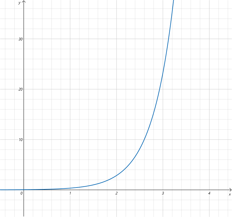
Ohm's Law still applies, of course, it's just that you can't easily predict the current flowing through a diode given only the voltage applied to it. It's an exponential curve and it varies by color and can even vary from part to part in the same run. A typical voltage/current graph for a LED might look like this:
You can see that as the voltage rises, the current gets quite out of control. If you dumped all 5V across the LED alone, you would find it glows brightly but briefly, and only once. I did this with my first LED. :) So that voltage needs to be limited. What's an electrical engineer to do?
The terminal hockey stick end of this graph is usually simplified into a parameter called the forward voltage drop. If we assume we're going to use the LED somewhere around its rated current, we can pretend that the voltage drop is constant and choose a resistor that gives us the current we desire. We have a 5V supply, and want a 3V blue LED to pass only 10mA (or 0.01A). Let's calculate a suitable resistance value to hit that target.
2V / x = 0.01A
x = 2V / 0.01A
x = 200Ω
So we need a resistor somewhere around 200Ω. If we use a more commonly available 220Ω resistor, the calculation changes slightly.
We can expect a blue LED to draw about 9.1mA with a 5V supply. But wait, the voltage drop changes depending on the color! Let's recalculate that with a 2V red LED.
3V / 220Ω = 0.0136A = 13.6mA
So paradoxically, a lower voltage red LED will use more power with the same resistor. Ideally, you'd adjust the current limiting diodes to compensate but for simplicity, they're all the same in this design (even more ideally you'd use a constant-current driver but that's a whole other bag of worms). Still, we're quite a bit below 20mA so we'll be just fine.
As a final note, there are many ways to limit the current across an LED. A resistor just happens to be the simplest and cheapest.
But what is happening, really?
You may have picked up on the flaw in this approximation. The current across the LED depends on the voltage across the resistor, but the voltage across the resistor depends on the current. We're stuck in a loop! What do we do? Well we could do a lot more math and calculate it exactly based on the exact mathematical relationship between the LED's voltage and current. But in practice we don't bother because we have multimeters! Let's ask the circuit what's going on!
The great thing about having a resistor in series with the LED is that through Ohm's Law, it can tell us what the current is as long as we know its resistance and the voltage across it. Both are easily tested with any multimeter.
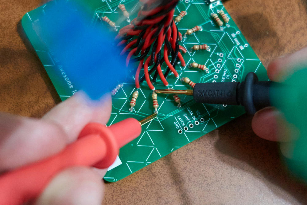
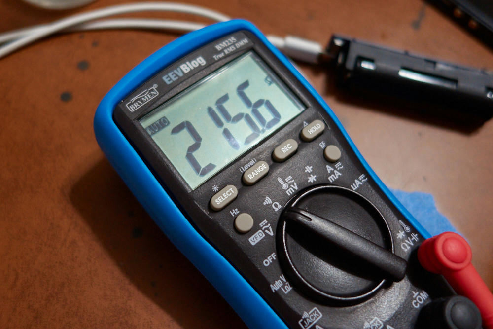
First, we need to know what the resistance of the resistor is. Pick any resistor and check it with the power disconnected from the LED Tree.
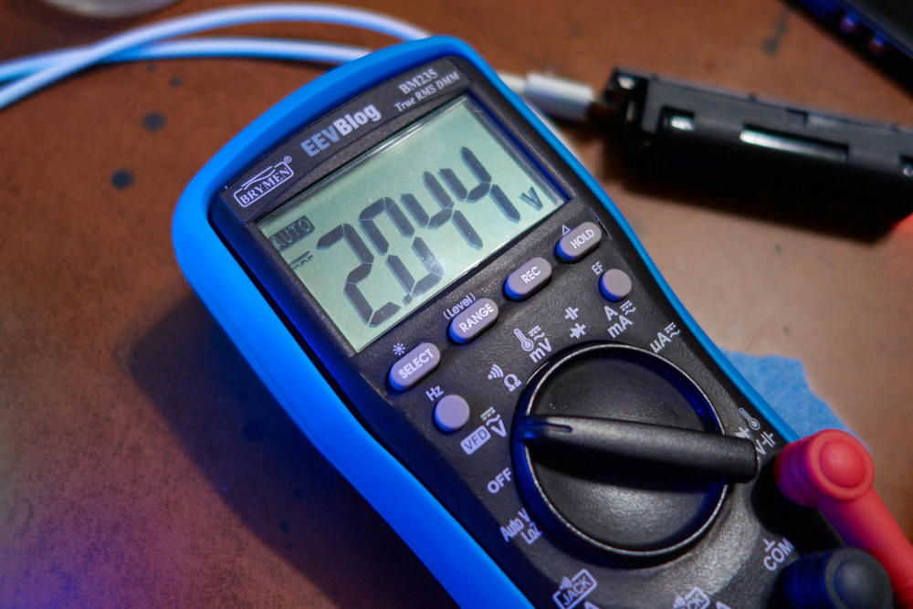
Here I get 215.6Ω. Now turn the circuit on and measure the voltage across the same resistor.
2.044V. Now we just plug into Ohm's Law to find the current.
I = V / R
I = 2.044 / 215.6
I = 0.0095A = 9.5mA
Because they're in series, the current through the LED must be the same as the current through the resistor. So the current through this LED is 9.5mA! Easy!
Digital Control
The really exciting part is that with a handful of extra parts, you can plug these LEDs into an Arduino or Raspberry Pi or other microcontrollery thing of your choice and turn the LEDs on and off with code.
First, let's talk about shift registers and why you might need them.
The 74HC595 and You
If you've worked with an Arduino, your first thought is probably "Why can't we just plug all the LEDs into the pins of the Arduino?" And the answer is you totally can! A lot of microcontrollers have enough pins to drive sixteen LEDs or more. And something like the ATmega328P used in the Arduino can supply more than enough current per pin (40mA maximum) and in total (200mA maximum) to drive 16 LEDs, provided you've limited the current on each LED to 12.5mA or less. You wind up in a bit more trouble when you use a Rasbperry Pi, which can source enough current per pin (16mA) but is much more limited in total (50mA). Not to mention its pins will only provide 3.3V, meaning you have to choose smaller resistors to get that current anyway. And if you use something like an ATtiny, you won't have enough pins to start with. So sometimes you will need to offload the I/O duties to something else. Enter the shift register.
How do you control more pins than you have? You make a tradeoff — you use a few pins to communicate the outputs you want, one after the other, to a device that will output those on its own set of pins. A shift register is a device that turns a serial input into a parallel output (the inverse exists as well!). We have to have one pin with our data, and another pin to tell the device when to shift that value into the next position. This second pin is the clock.
It might also be nice if the outputs didn't change until we shifted everything into place. This behavior is called latching, and we use a third pin to tell the device when to do that. Not all shift registers have this capability but the 74HC595 does and it's pretty handy.
Each 74HC595 has eight outputs labeled QA through QH and the LED Tree has room for two of them. Doesn't that mean we need a set of data, clock, and latch pins for each one? No, actually! This is what makes shift registers really neat devices — there is usually an output (labeled QH' in the 74HC595) that you can connect to the input of a second shift register, turning two of them into a single 16 output shift register. And you can keep chaining that as long as you want! (Well okay, you run into problems eventually but not in anything you'll make on a single circuit board...)
Shifting Bits
So how do you interface these shift registers to your Arduino or similar? Well you need to allocate three pins for the three tasks, data, clock, and latch. Set the data pin and pulse the clock pin to shift in one bit. Repeat that eight times and your shift register is fully loaded. Then pulse the latch pin and you'll find the LEDs you selected lit up. Let's go over that in a bit more detail.
I'll use the Arduino programming APIs to demonstrate, but this will work with whatever GPIO output method you have available.
First, set up your pins.
// It's good practice to define some constants for
// your commonly-used pins. I've chosen these pins
// randomly; use what works best for you.
#define DATA  2
#define CLOCK 3
#define LATCH 4

void setup() {
  // Set all of these to be output pins
  pinMode(DATA, OUTPUT);
  pinMode(CLOCK, OUTPUT);
  pinMode(LATCH, OUTPUT);

  // Make sure clock and latch are low to start.
  digitalWrite(CLOCK, LOW);
  digitalWrite(LATCH, LOW);
}
Next let's create a function to shift one bit into the 74HC595.
void shiftBit(bool bit) {
  // set the data pin to our bit
  digitalWrite(DATA, bit);
  // pulse the clock pin
  digitalWrite(CLOCK, HIGH);
  digitalWrite(CLOCK, LOW);
}
Next let's create a function that uses our bit shift routine to shift out a whole byte of values. There's a little bit of tricky bit manipulation going on here, but the important thing to understand is that each bit of the 8-bit input is shifted in turn, resulting in the least significant digit being output in QH and the most significant digit output in QA.
void shiftByte(uint8_t byte) {
  for (int i = 0; i < 8; i++) {
    // Select each bit of the input in turn
    bool bit = (byte >> i) & 1;
    // and shift it to our shift register
    shiftBit(bit);
  }
  // Then pulse the latch pin to output the values
  digitalWrite(LATCH, HIGH);
  digitalWrite(LATCH, LOW);
}
Now we have all the tools we need to control all 16 outputs. We just
have to output two bytes through shiftByte() and we're good to go!
void loop() {
  for (int i = 0; i < 2; i++) {
    // let's just use random numbers to blink
    // our LEDs randomly.
    uint8_t outputs = (uint8_t) random(255);
    shiftByte(outputs);
  }
  // wait one second until doing it all again
  delay(1000);
}
It's that simple!
Hacking
Adding Digital Control Components
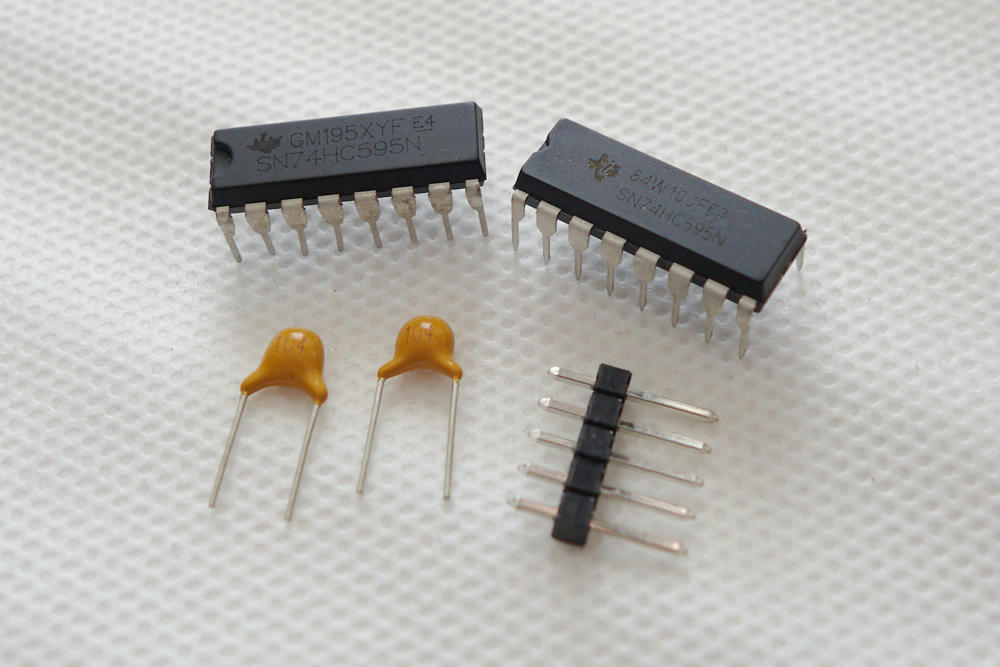
To add digital control, you need these parts:
- 2x 74HC595 chips in 16-pin DIP packages
- 2x 100nF capacitors (likely marked 104)
- 1 or 2x 5-pin 0.1" (2.54mm) spacing pin headers
The first and most important part is to cut the marked jumpers on the back of the board. The LEDs are by default connected to VCC via these jumpers and they must be disconnected in order to allow the 74HC595 to drive them. Just use a blade to make a clean cut. Be sure to double-check by using your multimeter to test for no continuity between VCC and the resistors!
Once that's done you just have to solder in the other components. If you only have one set of headers, solder them to the right side that has the DATA IN pin. That side is the one you'll connect to your controller.
You may find that your chips have the legs splayed outwards in a way that makes them difficult to get into the board. You will likely have to bend the pins inward to get it to fit. You can get dedicated tools for this but the simplest way is to just use pliers or set the chip sideways on a table and apply gentle pressure to bend them a bit.
Oh, and what are the capacitors for? When chips switch their outputs on and off, their power consumption changes. A 100nF capacitor next to the chip is a nearby power reservoir to make sure power supply issues don't cause logic errors. You could probably get by without them, but they're cheap and it's never a bad idea to include them.
Daisy-Chaining
Just like one 74HC595 is cascaded to the second, we can extend that chain to a second LED Tree via the DATA OUT pin. DATA OUT is connected to QH' on the second shift register. Just connect that to DATA IN on the second board (as well as the other pins), and now you have 32 LEDs to work with!
Also make sure that the wires connecting your trees can supply enough power. If they're too long or poor quality, resistance in the wires will lower the voltage and make trees further down the chain dimmer. It can also allow interference to introduce glitches into the digital control signals. I recommend stranded wire jumper cables, the thicker the better.
Power Options
Instead of using the USB type-C port as a power source, you can instead power the LED Tree via the either of the VCC/GND pins in the daisy chain connectors or the micro-B port, and use the type-C port as a power output. There are a couple of caveats to observe:
- Be sure that whatever power source you use is 5V and can provide sufficient current to power both the LED Tree and whatever device is plugged into the type-C port.
- Smarter devices will recognize the 5.1KΩ current sense resistors (R17 and R18) as a current sink and refuse to charge from the port. You may have to remove them.
To let smart devices recognize the LED Tree as a power source (which may be required for higher current charging), connect the left terminal of R17 and R18 to 56KΩ resistors, and connect the other end to VCC (pin 16 of U1 is probably the most viable choice on the board here). This will signal the availability of up to 500mA. Use 22KΩ for 1.5A and 10KΩ for 3A (though I don't recommend pushing 3A through this board as it wasn't really designed for high current).
If you'd like to add the missing USB type-C or micro-B connectors, the type-C connector is the CUI Devices UJC-HP-3-SMT-TR and the micro-B connector is the Amphenol 10118193 (though you can find many connectors with a similar form-factor).
