Joule Thief
Table of Contents
Overview
A joule thief is a self-oscillating step-up converter. The input voltage typically comes from a 1.5V alkaline cell, but the really interesting thing about a joule thief is it can run from even lower voltages — sometimes down to 0.6V! Because of this, it's also called a "vampire torch" since it sucks the remaining life out of batteries that would otherwise be considered dead (I mean vampires don't eat dead people but let's go with it).
Theory of Operation
The basic schematic for a joule thief looks like this. There are a few more footprints on this board, but we'll ignore them for now.

It's kind of an unassuming circuit. There's only five components, and strictly speaking, one isn't necessary. The centerpiece is the transformer, which is connected such that two windings are going in the opposite directions from the power input to the transistor and output. A NPN transistor's collector and base straddle the transformer. A resistor is connected from the power to the bottom side of the transformer that goes to the transistor's base. And there's an LED on the output, which connects to the transistor's collector and the top side of the transformer. The capacitor isn't necessary for the circuit to work, but it apparently improves efficiency through some mechanism I don't understand1.
The oscillation happens through a series of phases:
-
At first, no current flows through the top path, because the input voltage is too low to turn on the LED, and the transistor is off. Current begins flowing through the resistor, through the bottom winding of the transformer, and into the base of the transistor and out the emitter, turning the transistor on slightly.
-
As the transistor turns on, a larger amount of current begins to flow through the top winding of the transformer. This induces current in the bottom winding, which forces even more current into the transistor's base. This feedback loop continues to drive more and more current through the transformer.
-
Eventually the current in the top winding cannot increase any more. Since it is the change in flux that causes a transformer to transfer energy to other coils, this newfound stable point causes no more current to be induced in the bottom coil, reducing the current into the base of the transistor. The transistor begins turning off.
-
This of course causes the top winding's current to decrease, causing the same feedback in reverse. The base of the transistor becomes completely starved for current and the transistor shuts off completely.
-
The magnetic flux created by the earlier current collapses, inducing current in the top coil, which produces a voltage in the opposite direction. This voltage is added to the input voltage, creating a brief pulse at a voltage high enough to turn on the LED.
-
As this magnetic flux drains, the circuit returns to its initial state, and the cycle repeats.
The output is actually a series of pulses, which suits LEDs just fine. But you can also add a diode and a capacitor to create a stable (though still unregulated) voltage output. See the next section.
Build Options
The Joule Thief circuit board is designed to provide a variety of options for each component, to allow you to use the maximum amount of scavenged parts. It also offers some extra component options for various use cases. Added to the basic schematic above are an optional diode and capacitor, which turns the pulse output into a steady voltage, which is useful for driving microcontrollers or other things that don't work with pulsed power.

If you look at the full schematic you'll see there are even more components because almost every one provides multiple footprint options. Let's look at the board.
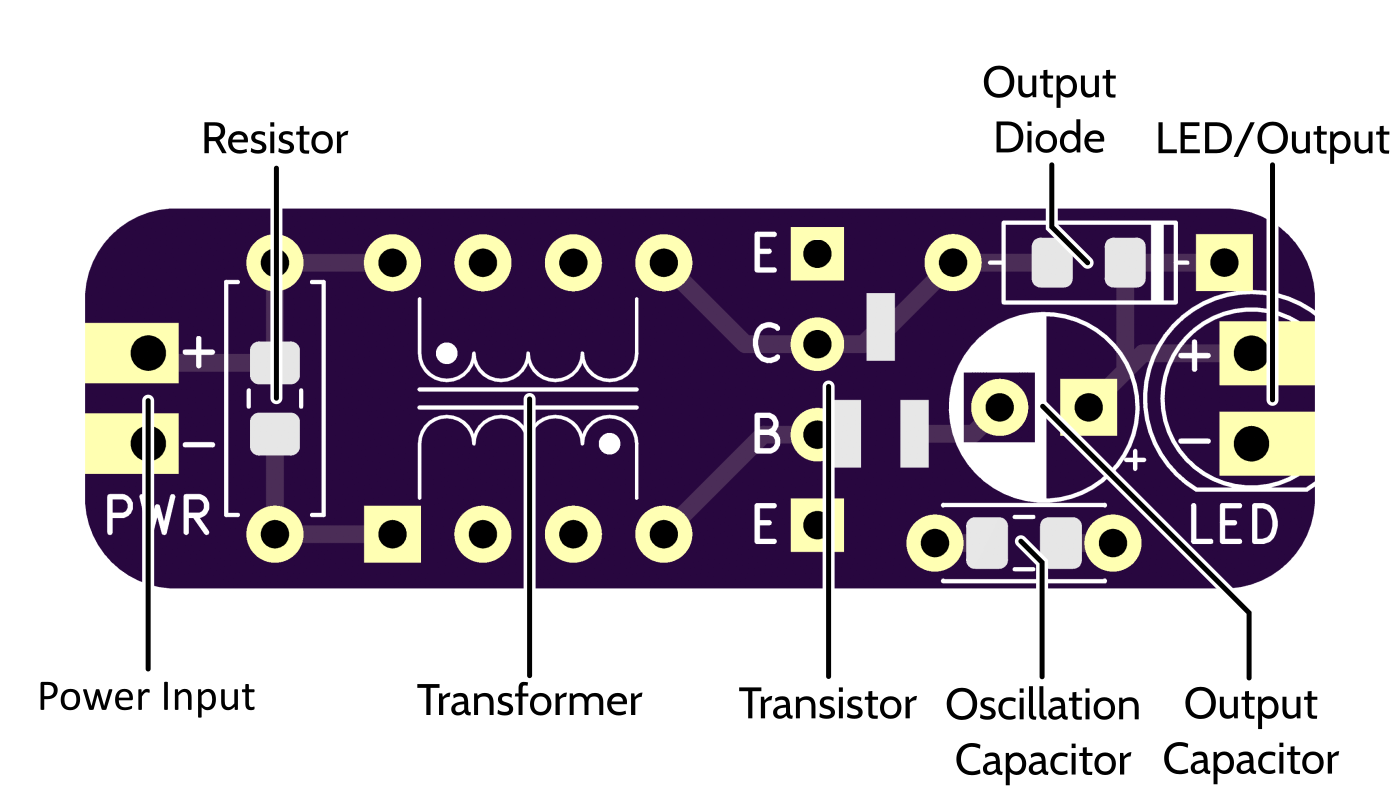
For the resistor, transistor, diode, and oscillation capacitor, you have the option of through-hole or 0805 SMD components. The transistor offers four through holes that allow any arrangement of emitter, collector, and base (thankfully, SOT-23 transistors appear to have standardized that). The transformer has a DIP-8 form factor for DIP-8 bobbins, but only the corners (pins 1, 4, 5, and 8) are connected. The power inputs and outputs are 0.1" spaced through holes, which can be used for many things including JST XH, 5mm LEDs, or DuPont connectors. The pads also go to the edge, offering other possibilities like just soldering on a LED lying on its side.
If you are just using an LED, remember to bridge across the diode pads, otherwise the LED won't be connected to the output.
Notes
- This was an innovation by Colin Mitchell, who added it to the circuit and was astounded to find this greatly improved efficiency by increasing the oscillation rate. Apparently incredulous that this had not been discovered before, he declares – "That's why you cannot trust anything or anyone. This improvement has never been presented in any circuit on the web. Obviously no-one has done any experimenting at all." Colin Mitchell is seemingly a bit of a crank.