BPS
Table of Contents
Theory of Operation
The BPS protects a single lithium cell against overvoltage, undervoltage, overcurrent, and short circuit using common DW01-type protection chips. The schematic is simple:
Current flows between B-, connected to the cell's negative terminal, and P-, the negative terminal of the pack. MOSFETs Q1A and Q1B control the flow of current, one controlling charging and one controlling discharging. R1 is connected to the positive terminal (which is the positive terminal for both the cell and the pack), and along with C1 provide a stable power supply as well as filtered voltage sensing at VCC. R2 acts as protection for the CS pin during charging under over-discharge, and current limiting for a charger connected backwards.
The DW01 detects current via the voltage drop between its GND and CS pins, which is the voltage drop across the MOSFETs. This means the effective current limit is influenced both by the chip's overcurrent limit (typically 150mV but many variants are available) but also by the on-state resistance (RDSon) of the MOSFETs you choose. And because current will be running through one of the MOSFETs in reverse, you also have to add the resistance of that. The DW01 datasheet estimates this by doubling the RDSon value which I guess is fine but I don't know if it's accurate. So if your control chip has a discharge limit of 150mV and your MOSFETs have an on-state resistance of 20mΩ -
then the overcurrent limit is 3.75A.
Connections
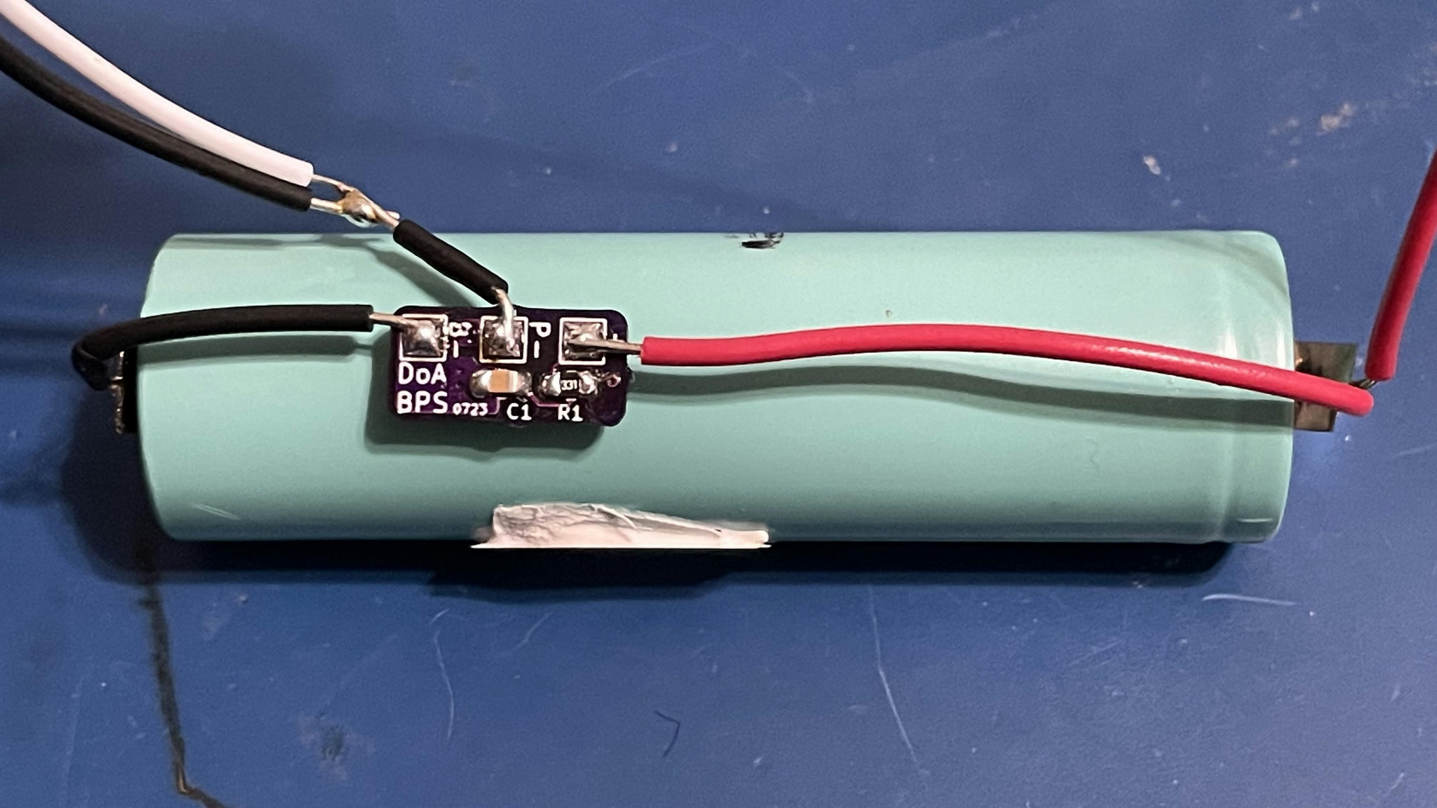
The B- terminal should go directly to the negative terminal of the cell. You could solder it directly to the battery if you want, but be careful not to short anything else against it. If B- and P- are connected, the battery protection will be rendered moot.
The P- terminal becomes the negative terminal of your battery pack. You can see here that it connects to an NTC thermistor and sends two wires to the device.
The + terminal connects directly to the positive terminal of the cell, which is also the positive terminal of the pack.

