Belmont
Table of Contents
This manual describes version 1 of the Belmont USB Hub.
Features
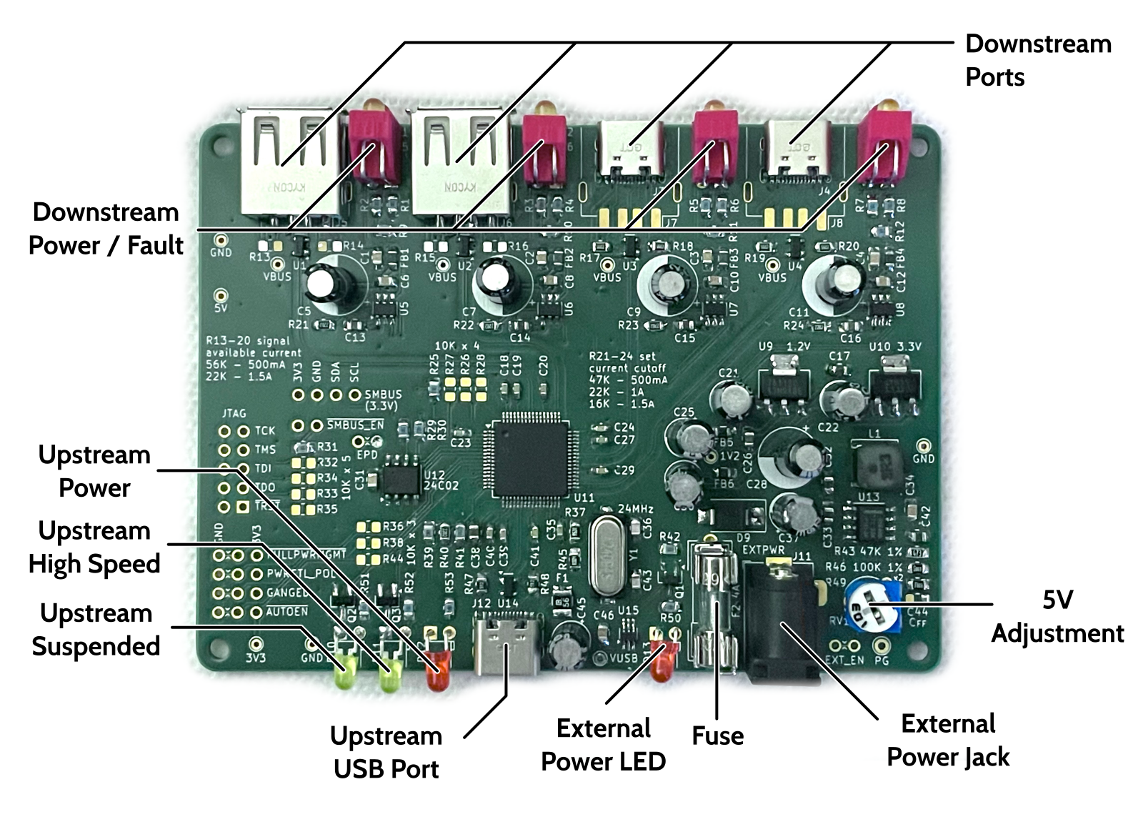
The Belmont is a 4-port hub with a type-C upstream port. The downstream ports may be either type-A or type-C jacks. Next to each port are two LED indicators. The top one indicates that the port is powered. The bottom one indicates that the port has a power fault as reported by the power monitoring chips on each port. If the programmed current limit is exceeded, power will be cut and the fault light will light briefly before the hub disables power to the port.
Optionally, an external power supply can be connected to the external power jack. Belmont will operate with any supply from 6-24V through a standard center-positive 5.5mm barrel jack.
There are two power LEDs. The one just to the left of the upstream USB jack indicates that 5V is supplied from the upstream USB host. The one to the left of the fuse indicates that the external power is connected and it is supplying 5V instead of the upstream USB power.
To the left of the upstream power LED are two indicator LEDs. The one to the left indicates that the upstream host has suspended the hub. And the one to the right indicates that the upstream is operating in High Speed mode.
Theory of Operation
At its heart, this is a pretty simple device. Plug one end into a USB host. Plug devices into the downstream ports. It's a hub. But let's discuss the finer points of the design.
Power Switching
5V power can be provided from either the upstream USB port or from regulated external power. There is a LM66100 "ideal diode" that switches between these two sources. It disconnects the USB 5V when the regulated 5V is higher than the USB 5V, and the state of this switching is reflected in the external power LED. If the LED is on, the ideal diode is switched off and the hub is powered from external power. If the LED is off, the ideal diode is switched on and the hub is powered from the upstream USB port.
Power Regulation
Primary 5V power is provided through the switched sources mentioned above.
The external power regulator is a LMR33640 buck regulator. It has a fairly wide voltage range that goes up to 36V. Unfortunately, not everything on the board is rated that high, so the input has been conservatively specified at a max of 24V. External power goes through a 5x15mm (2AG) fuse. It is recommended that you use a 3A fuse for standard downstream USB power (500mA per port). Likewise, the external power supply should be able to supply at least 12W to cover the power requirements of all four ports and conversion losses.
RV1 can be turned to adjust the 5V regulator output level from about 4.5 to 5.5V. It is recommended that 5V is adjusted to above 5.15V to put it out of the hysteresis range of the LM66100 (though this will depend on the voltage provided via USB so this is not a perfect solution!).
The TUSB4041 also requires 3.3 and 1.1V rails which are provided by two standard linear regulators. The 1.1V rail is actually provided by a 1.2V regulator, which is technically still in spec as long as it's below 1.26V.
Upstream USB
The upstream type-C port has standard 5.1K pull-down resistors to signal power to an upstream smart host. There is a 3A polyfuse protecting this input. The upstream port (and all ports) have a TVS diode array to protect against ESD from plugging in cables.
Downstream USB
Each downstream port is powered by the 5V supply, and power is switched by a TPS2552D controlled by the TUSB4041. Each port has its own decoupling capacitors and a ferrite bead to decouple power noise from downstream devices.
Two LEDs are provided to indicate status. One is powered directly from
the switched port power, and indicates that power is on for that port.
The second one is connected to the FAULT output of the TPS2552D, and
lights when it detects an overcurrent event. In practice, this is a very
brief event and you'll only see a brief flash before the TUSB4041
disables power to the port.
TUSB4041
The TUSB4041 is configured through a combination of strapping pins, EEPROM, or SMBus configuration. This board is designed to be configured via EEPROM, but it provides headers for SMBus and strapping headers in case those are useful.
The EEPROM only needs to be 256 bytes (a 24C02). There is an EEPROM Power Disconnect jumper provided to disconnect the EEPROM from system power. But in practice this isn't a problem. The TUSB4041 reads from the EEPROM on startup when is strapped high on startup. This may corrupt a read or write that happens shortly after power is applied, but the EEPROM is idle after that.
The most important feature that needs to be configured is swapping the port polarity on all the ports. The board design flips the differential pairs to simplify routing and there is no strapping pin to configure this.
A default EEPROM configuration is provided in the Files section, which enables a set of reasonable features. The EEPROM configuration is described in more detail below.
A JTAG breakout is provided for giggles. The datasheet says nothing about it, but the evaluation board had it so I wired it out of curiosity.
Build and Configuration
There are a few build-time options and several EEPROM configuration options.
Power
Strictly speaking, the external power section is not required. If you want something that is powered only by the upstream USB port, you can omit J11, F2, D9, C33, C37, U13, C34, L1, C44, R49, R46, RV1, R42, R43, Q1, R50, and D13.
Downstream USB Ports
Each downstream port has a footprint for both type-A and type-C ports. Even though the type-C port fits inside the type-A port, the type-A jacks should have a plastic bottom that raises the metal shell off of the board, so there should be no risk of shorting the type-C pads.
There are two important programming resistors per port. R13-R20 are the CC pull-up resistors, which tell the downstream device how much power is available on this port. CC pull-ups only need to be fitted on type-C ports. Type-A ports have no such power signaling. Use values for these signaled power levels:
| Pull-Up Resistance | Signaled Available Current |
|---|---|
| 56K | 500mA |
| 22K | 1.5A |
| 10K | 3.0A (not recommended for this board) |
The other important resistors set the current limit on the TPS2552D power controllers.
| Resistance | Current Limit |
|---|---|
| 47K | 500mA |
| 22K | 1A |
| 16K | 1.5A |
This is based on a formula you can find in the datasheet. If you want higher current limits, you can swap in the pin-compatible TPS25221 which is limited to 2.7A and can supply 2A continuously.
EEPROM Configuration
The provided EEPROM configuration sets these basic values:
| Register Address | Name | Value | Description |
|---|---|---|---|
| 0h | Signature | 55h | Marks the EEPROM as valid configuration data |
| 01-02h | Vendor ID | 0451h | little-endian (default value) |
| 03-04h | Product ID | 8140h | little-endian (SEE DATASHEET FOR DETAILS ABOUT THE FLIPPED BIT) |
| 05h | Device Configuration | 00h | default values |
| 06h | Battery Charging | 00h | disabled on all ports |
| 07h | Device Removable | 8Fh | all ports removable |
| 08h | Port Used | 0Fh | all ports used |
| 0Ah | Device Configuration 2 | 00h | default values |
| 0Bh | Port Polarity | 9Fh | All ports flipped |
| 20-21h | Language ID | 0409h | little-endian, set to US English |
| F0h | Additional Feature | 10h | Sets status output for upstream port |
All other values are zero.
You can configure a lot more features like the strings and battery charging configuration. See the datasheet.